Modulus of Subgrade Reaction is an important soil parameter used in Structural and Geotechnical Engineering. It is used in conjunction with a soils allowable bearing capacity to design footings and rigid pavements. So what exactly is the Modulus of Subgrade Reaction?…
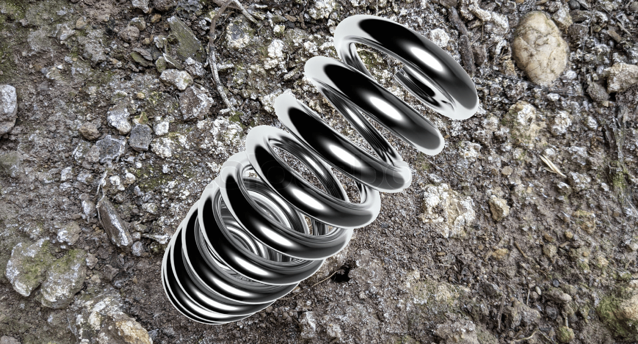
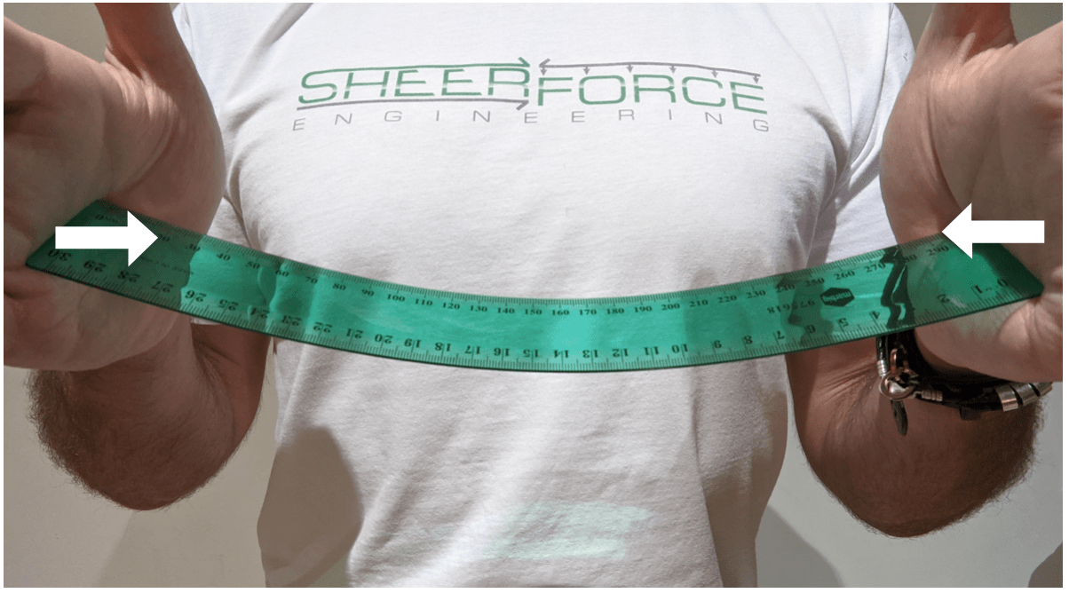
The Modulus of Subgrade Reaction is a measure of a soils stiffness. It is an indicator of a soils resultant unit displacement under a given pressure. The units of Modulus of Subgrade Reaction are often expressed as kPa/mm, MPa/mm or pci (kilopascal per millimetre, megapascal per millimetre and pound per cubic inch respectively). It is also often referred to as soil spring stiffness and is used by Structural Engineers as part of their analysis to predict a footing or pavements settlement under a given design loading. The higher the Modulus of Subgrade, the stiffer the soil is.
Soil Stiffness Equation
The Modulus of subgrade is simply a unit displacement of soil under a given applied pressure. This is represented by the equation below…
This soil stiffness property “k” is determined using fiend testing (covered later in this article).
What are the Units for Modulus of Subgrade Reaction
There are quite a number of units which are used to express the Modulus of Subgrade Reaction and this can get rather confusing.
Re-visiting the introduction to this article for the explanation of soil spring stiffness helps us to better understand its units… “a measure of a soils unit displacement under a given pressure”. Lets now take a look at an example soil spring stiffness value and un-pack it a little further…
This is a soil stiffness for a weak clay material given as 12,000kPa/mm. In real terms this means that for every 12,000kPa applied to the soil (kilonewton per meter squared), the soil is expected to displace or settle 1mm.
You may also see this soil property expressed in other units such as kN/m3 or N/mm3 (kilonewton per cubic metre or newton per cubic millimetre respectively). This can further complicate the matter however MPa/mm is exactly the same as N/mm3. This is because MPa/mm is essentially the same as N/mm2/mm which is the same as N/mm3. The next section of this article provides a handy unit conversion table for your reference…
Unit Conversion for Modulus of Subgrade Reaction
Here are some common units used for soil spring stiffness with their respective unit conversions…
| UNIT | EQUIVALENT UNIT |
| 1 kPA/mm | 0.001 MPa/mm |
| 1 kPa/m | 0.0000001 MPa/mm |
| 1 kPa/mm | 1000 kPa/m |
| 1 MPa/mm | 1000 kPa/mm |
| 1 MPa/mm | 1000000 kPa/m |
| 1 Mpa/mm | 1000 MPa/m |
| 1 kPa/m | 1 kN/m3 |
| 1 MPa/mm | 1 N/mm3 |
| 1 kPa/m | 0.0037pci (lb/in3) |
| 1 MPa/m | 3.68pci (lb/in3) |
What are the Expected Values for Modulus of Subgrade Reaction
The value for soil spring stiffness is acquired by site testing performed by a qualified Geotechnical Engineer.
As a general guide however, here are some ranges of values you can expect for different soil conditions…
| Soil Type | Modulus of Subgrade (kPa/m) | Modulus of Subgrade (MPa/mm) |
| Compacted Sand | 50,000 – 150,000 | 0.05 – 0.15 |
| Clay | 80,000 – 100,000 | 0.08 – 0.10 |
| Crushed Stone | 100,000 – 150,000 | 0.10 – 0.15 |
| Corse Crushed Stone | 200,000 – 250,000 | 0.20 – 0.25 |
How is the Modulus of Subgrade Reaction used in Footing Design
The Modulus of Subgrade is an important factor in the design of footings and rigid pavements.
Structural Engineers use this soil stiffness parameter for footings which are sensitive to movement or supporting critical infrastructure.
The soil stiffness properties are often modelled in an FEA design software along with the footing itself. The modelling of this support condition is usually simplified by a series of point spring supports or depending on the software a spring area support. For a step-by-step example of this process, take a look at THIS article where I perform this check on a strip footing using RAM Concept.
A change in soil stiffness can drastically alter the distribution of the resultant pressure applied from the footing to the soil. The deign of critical foundations involves a collaboration between both the Structural and Geotechnical engineers. The example below shows two isolated pad footings which are identical both in dimensions and applied loading however the footing on the right has twice the soil stiffness as the footing on the left. As you can see, the stress distribution is quite different not only in shape but magnitude when comparing the two…
How is Soil Stiffness Determined or Measured?
The Modulus of Subgrade Reaction is determined using a field plate load test. The plate load test is performed to determine the ultimate bearing capacity of the soil and the probable settlement under the given load. This test type is often used to determine soil capacities and stiffness’s for shallow footing systems.
A stiff plate (usually steel) is placed on the proposed soil at a given founding depth. This often requires the digging of a trench to the proposed founding depth of the proposed future footings. A load is then gradually applied to the plate and the settlement is recorded at each incremental load increase. This is somewhat similar to how deep pile foundations are tested for strength and serviceability (for more information on how foundation piles are tested in the field take a look at THIS article).
When the soil begins to “fail” during this field test, exponentially higher settlements are recorded for the same given load incremental increase. The total load applied to the plate at the beginning of this exponential increase is recorded and the magnitude is divided by the area of the plate. This value represents the soils ultimate bearing capacity. A safety factor is then applied to this value to obtain the safe bearing capacity (usually a safety factor anywhere from 2 to 3).