Due to the nature of concrete construction and how its formed on-site. Concrete buildings need to to be constructed in portions and stitched together. The result is much like a patchwork quilt of smaller components coming together to form one larger entity greater than the sum of its parts. What allows this segmented construction to occur are construction joints. This article takes a look at the construction joint in slabs in particular…
What is a construction joint in slabs you may ask?…
A construction joint in concrete slabs is a junction where two separate constructed portions meet. Due to the nature of concrete placement, a finite volume of concrete can be poured in any given day. This restriction requires that some larger concrete elements, particularly concrete slabs, are divided into smaller portions. The separate slab portions are structurally connected together at the construction joint. A construction joint in slabs generally comprises reinforcing bar across the joint to transmit the required tension loads as well as some form of interlocking key our roughening which facilitates the transfer of shear forces.
This article will cover the construction joints in slabs for several different applications. Use the list below to jump straight to the element which most interests you. Or for the full learning experience simply read from start to finish:
- Construction joint in slab on grade (pavement slabs)
- Construction joint in suspended slabs
- Construction joint in suspended slabs at steps or folds
Incidentally, a poorly detailed construction joint was found to be a primary reason for the collapse of the FIU pedestrian bridge in Florida. To learn more about the Structural reasons for the collapse take a look at THIS article.
When is a Construction Joint Required in Slabs
There are a number of reasons why a construction joint may need to be introduced into concrete slabs…
Volume Limits of Concrete Pour
The requirement for construction joints in slabs can be heavily dependant on the possible daily concrete volume which can be poured for a given site.
Factors which influence the volume of concrete which may be poured through an entire day may include:
- Access to the site and how many concrete trucks can enter or leave at any given time
- How many concrete pumps can be used simultaneously at any given time for the given site
- The size of the workforce on-site. Placement of concrete requires individuals who can trowel and place the concrete while it is being poured.
Larger concrete volumes can be achieved if concrete placement can continue around the clock. Most local government restrictions and union requirements don’t always allow this to occur however.
When sizing a slab, a good rule of thumb during concepting is to allow for a construction joint in slabs for every 500m3 of concrete being placed (17,655 ft3 ). This allows for an 8 to 9 hour working day with usage of two concrete pumps and allows time for trowelling and initial beginnings of the curing process.
The concrete pour volume allowance can be further negotiated with the contractor once they have been engaged and the construction management plan has been finalised. In the beginnings of design however, it is better to be slightly conservative on your construction joint assumptions for slabs.
Reduce Shrinkage Cracking
During the hydration process, the concrete begins to dry as the water is both taken up by the cement paste and also drawn out of the concrete by the curing process. The drying of the concrete causes shrinkage to occur within the slab.
The apparent shrinkage can be further increased in post-tensioned slabs. In these settings, the elastic shortening of the slab due to the application of the post-tensioning load can make the shrinkage effects worse. (For a detailed article on how a post-tensioned concert slab works, take a look at THIS article)
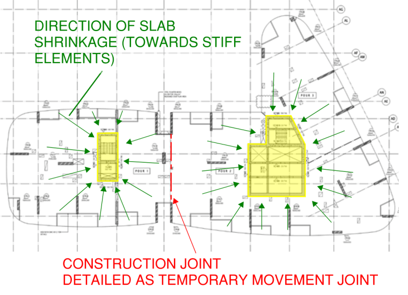
If a single slab is being poured between two very stiff lateral elements, this can cause excessive cracking within the slab. It can also result in loss of effective post-tensioning force in PT slabs. In this case, a construction joint can be provided in the slab which allows temporary movement and facilitation of shrinkage. The construction joint can then be structurally connected after a sufficient period of time (after the majority of the shrinkage effects have occurred).
This special type of construction joint in slabs is often referred to as a temporary movement joint. Take the example floorplate below where the slab structurally connects a main building core as well as a lesser fire escape stair core. The lateral stiffness of these elements are significant and require the temporary movement joint to be introduced or else a major crack may form directly between the two during construction…
Construction Joint due to Emergency Situations
Sometimes a construction joint in slabs needs to be introduced at very short notice. I have been at the receiving end of many early morning phone calls from site. The request often comes while concrete is being poured to introduce an un-planned construction joint due to any number of the following reasons (and more!):
- Significant traffic may be preventing some of the concrete trucks to arrive on-site in-time.
- An unforeseen weather event may arrive which prevents further pouring and curing of the slab
- There may be a machinery break-down for example the concrete pumps may not be operational.
- There may be a fire nearby which causes an evacuation to occur on the construction site.
In these cases, you need to think on your feet as a Structural Engineer and provide quick advice on the best location to introduce the construction joint and what reinforcement detailing to provide. The later sections in this article go through the structural design approach for checking a given construction joint in slabs.
Construction Joint in Slab on Grade
Slab on grade elements (sometimes called pavement slabs) are usually thinner than suspended slabs.
Slab on grade elements can be found in warehouses, and car parks.
The unique problem with pavement slabs in a buildings setting is that they are often restrained by very stiff elements such as column and wall foundations. The pavement slab is usually poured directly above these footings and also poured around load-bearing columns and walls.
It is at these locations where the pavement slab is susceptible to cracking.
For this reason Structural Engineers are required to specify construction joint details and locations to prevent this cracking from occurring. These are usually supplemented with saw-cut joints within the slab as well.
These joints are positioned in such a way as to allow the pavement slab to shrink away from the stiff restraining elements therefore preventing the cracks from occurring.
The construction joint in the slab needs to allow for horizontal movement of the slab while at the same time prevent differential vertical movement from occurring between slab segments. This is especially important for warehouse slab applications where the racking system and trolley jacks require smoother surfaces to operate upon.
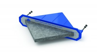
A system which I have used a number of times in the past is the diamond dowel by Danley. The dowel is a diamond shaped steel plate. A diamond shaped sleeve is cast into one slab pour and a diamond shaped steel plate cast-into the next adjacent slab.
The diamond arrangement allows differential movement for slab elements moving away from the construction joint as well as along the construction joint. At the same time it transfers vertical load which prevents differential settlement to occur in the vertical direction.

Construction Joint in Suspended Slabs
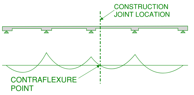
Firstly, determining the location of a construction joint in slabs is critical. The construction joint should ideally be located at the position of lowest stress in order to reduce the load demand on the joint.
In a continuous slab, this is the point of contraflexure (i.e. the point at which the bending moment transitions from positive to negative and is essentially zero). As a rule of thumb, this is somewhere in the vicinity of one quarter to one third of the total span in question. This is illustrated in the arrangement below…
After the position has been determined, the joint itself can then be detailed. A conventional construction joint in slabs which are suspended generally contain a shear key to assist in transferring shear loads as well as reinforcement to tie both pours together and support any residual tension loads which may exist across the joint.
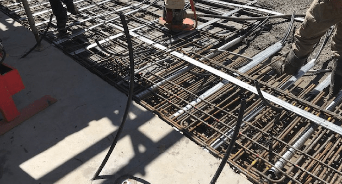
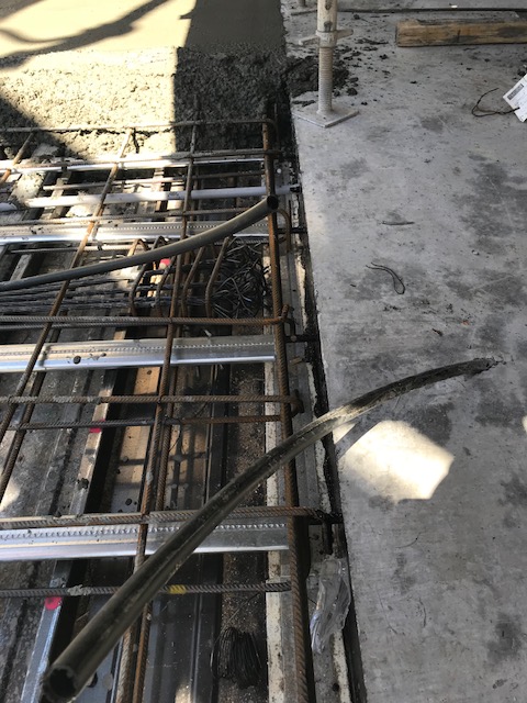
Depending on the stresses which are required to be transferred through the construction joint, either a central layer of reinforcement is provided or a top and bottom layer. The image below shows an example arrangement of this with two layers of reinforcement indicated.
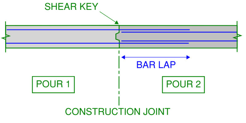
The reinforcement for pour 1 protrudes through the temporary formwork to provide connection to pour 2. Bars are then lapped together in this zone to ensure continuity of reinforcement. For a full article on bar development and pull-out failure, take a look at THIS article which discusses failure mechanisms of reinforcement in tension.
Once the tension reinforcement has been sized based on the loads through the joint, the shear capacity can then be calculated. It should be noted that even if the joint is located at the point of contraflexure (zero bending moment) there is still likely to be moderately high shear forces through the joint which need to be addressed.
The check we are required to perform is the shear interface between two planes. This can be found in chapter 11.6.4 of ACI 318-08 (a similar approach is outlined in the Australian Concrete code AS3600)…

Where:
- Avf = Cross-sectional area of reinforcement passing through the joint
- fy = Yield Strength of the reinforcing bar through the joint
- μ = Coefficient of Friction
The coefficient of friction (μ) is a measure of how rough the interface between the two pours are. It is encouraged that the face of the first pour be intentionally roughened in order to improve the coefficient of friction for the joint. Below is a table for a range of values for μ taken from the ACI (American concrete design code).
| Application | Coefficient of Friction (μ) |
| Concrete placed monolithically (i.e. no joint) | 1.4 |
| Concrete placed against hardened concrete surface intentionally roughened | 1.0 |
| Concrete placed against hardened concrete not intentionally roughened | 0.6 |
| Concrete anchored to as-rolled structural steel by headed studs or by reinforcing bars | 0.7 |
For a worked example on this check based on the ACI code (which is similar in approach to the Australian concrete code) take a look at THIS article which covers the structural reasons why the FIU pedestrian bridge collapsed in Florida.
Construction Joint in Slabs at Steps (or Folds)
In a perfect world, all slabs would be easy to build and flat. Unfortunately in the real world environment this is not always the case.
On most building projects, the most complex slab in the building from a Structural Engineering perspective is the ground floor slab. This is because:
- The ground floor slab is often a place where transfer columns and therefore transfer beams are required (for an in-depth article on transfer beams, take a look at THIS link where i cover transfer beams and design considerations which need to be adopted).
- Ground floors generally have varying uses from entry lobbies, to retail, to bin store rooms, to plant rooms. All of these different uses have different floor finishes and therefore different set-down requirements for the primary slab.
- The ground floor slab is generally required to match the surrounding natural ground level to allow at grade entry into the building. If the building is constructed on land which is not level, this may result in several steps (often called folds) being required in the slab.
The final dot-point above can be an automatic trigger for the introduction of a construction joint in slabs. Depending on how large the change in level is, it may need to be constructed in several pours to be physically buildable.
Lets take a look at an example slab which has a relatively large step in it…
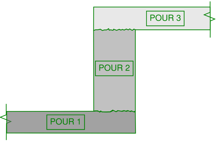
In the extreme example above, the slab needs to be constructed in three sections thus requiring more than one construction joint to be introduced. For constructability, the lowest portion of the slab is generally constructed first, followed by the “fold” (which resembles a mini wall) then lastly the top slab on the high side of the step.
Lets now take a look at how to detail a construction joint in slabs with steps. Lets consider a simply supported slab span of 8m (26.2 ft). A slab step is required at mid-span. This requires the introduction of two construction joints in the slab (resulting in three slab pours as per the previous image). In summary, we will also consider the following:
- 250mm thick slab
- Consider a unit width strip of slab (1m or 3.3 ft)
- Self-weight considered only
- No load factors (as these will vary depending on the region you are in)
- Simply supported condition (pin and roller support ends)
- For simplicity, we will ignore the additional self-weight of the slab fold for this exercise.
- Concrete cover to primary reinforcement is 30mm (1.2 inch)
- Reinforcement grade used in the slab is 500MPa (72,500 psi)
Now lets take a look at what the bending moment diagram would look like for this arrangement both with and without the slab step…
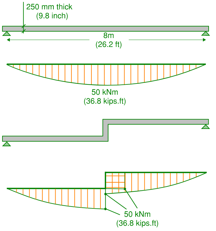
We know that the bending moment in the vicinity of this step and therefore passing through the construction joints in the slab is 50kNm (36.8 kips.ft). We can now zoom in on the step location and start to detail the reinforcement passing through the construction joint…
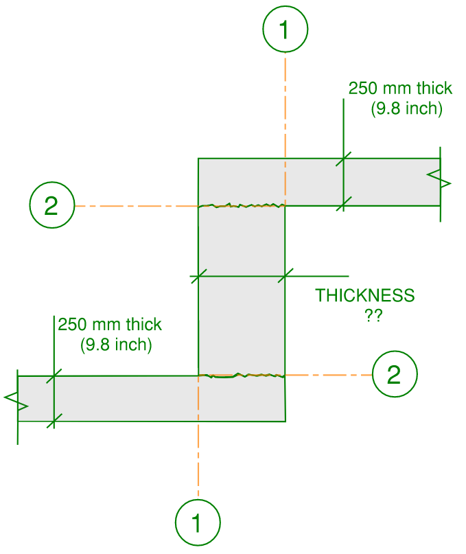
There are two critical bending moment planes we need to check, these are designated as grid lines 1 and 2 on the image above. The design and detailing of the reinforcement for the bottom construction joint can be mirrored to the top construction joint. The slab fold thickness is designated as “un-known”, this dimension will need to be verified. We will first assume that the 250mm thickness of the adjacent slab is continued through the fold and check its adequacy.
For a 250mm thick slab and 50kNm of bending moment we can determine the reinforcement requirement as follows (in mm2 for our 1m wide slab portion)…
Ast = 50,000,000 / (0.85 x 0.8 x 500 x 220) = 668mm2
An N16 reinforcing bar (16mm diameter) spaced at 300mm intervals will give us 670mm2 of reinforcement. So lets adopt this as our reinforcement detail. Now lets check our first critical moment plane number 1 to make sure that the N16 bars are fully developed at this face…
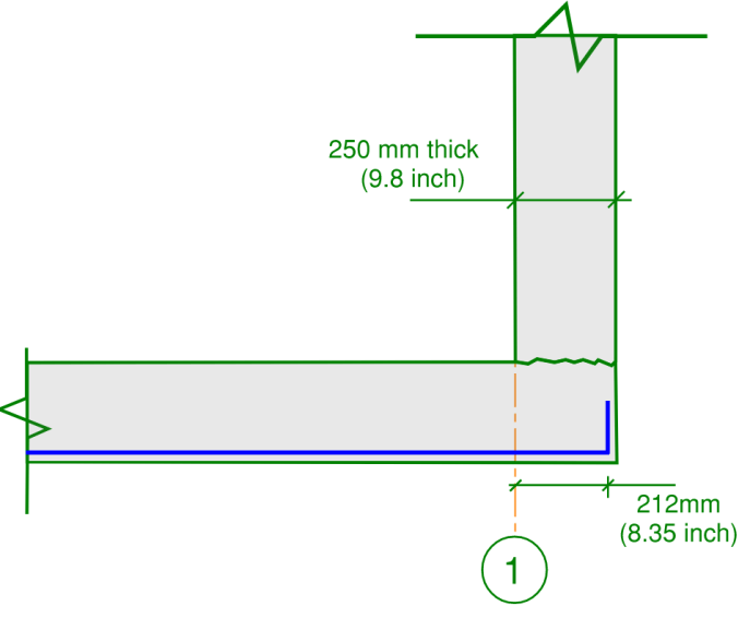
First we will assume that the fold thickness is 250mm. Therefore the development length of the reinforcing bar is 250 – 30 (cover) – 8 (radius of bar) = 212mm (or 8.35 inch)…
The development length of a reinforcing bar in tension can be roughly approximated to be 40 multiplied by the bar diameter. (note that more rigorous analysis can be performed and guidance is provide in both the ACI and Australian concrete codes). Therefore the development length required is 40 x 16 = 640mm (25.2 inch). With a standard cog on the end (90 degree bend in accordance with code requirements), this allows the development length to be halved which leaves 320mm.
From this we see that the fold width of 250mm is not adequate to allow full bar development at the critical face number 1. Therefore the fold thickness should be…
320 + 30 (cover) + 8 (bar radius) = 358mm.
Lets round up the fold thickness to 380mm for simplicity.
Now we can check the critical bending moment face 2 using a similar approach. The critical bending moment face 2 corresponds with the construction joint in the slab. This time our effective depth in bending is 380 – 30 (cover) – 8 (bar radius) = 342mm
We wish to use the same reinforcing bar which is in the adjacent slab through the fold to make construction simple. Therefore we will re-arrange the previous equation to solve for bending moment capacity…
ΦM = 670 x 342 x 0.85 x 0.8 x 500 = 78 kNm (58 kips.ft)
This is higher than the applied bending moment of 50kNm so the design is adequate. However what about the development of these bars?…
Because the development of this bar is controlled by the adjacent slab thickness (which is 250mm) we are again left with 212mm of development length as illustrated below…
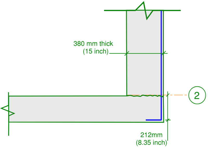
The development length required is again 40 x 16 = 640mm divided by 2 due to a 90 degree cog being provide leaves a required development length of 320mm.
This means that the provide development length is 35% too short. However full development of the reinforcing bar is not required for the design to be adequate. You will recall that if the bar is fully developed we achieve a bending moment capacity of 77kNm. Reducing this by 35% to account for the under-developed bars gives 50kNm which is the exact capacity required and equal to the design bending moment.
We have now verified the detailing of reinforcement in a construction joint in slabs with steps (folds) introduced to them.

