The footing of a structure is arguably the most important element. Without strong footings, the structure above will simply not work. This article covers the design philosophy and approach to analysing an isolated footing using the Australian concrete code AS3600.
Sheer Force Engineering has covered a number of articles associated with footings and foundations. If you enjoy this article, you may also find the following topics interesting…
- FOOTING DESIGN IN RAM CONCEPT – Sheer Force Engineering
- PILE FOUNDATION TYPES AND THEIR BENEFITS – Sheer Force Engineering
- TYPES OF PILE TESTING AND WHY THEY ARE NEEDED – Sheer Force Engineering
- IS TOP REINFORCEMENT REQUIRED IN ISOLATED FOOTINGS – Sheer Force Engineering
First we will take a look at the design approach to isolated pad footings. Then we will take a look at a pad footing design spreadsheet tool imbedded right in this article. Finally, we will then role up our sleeves and look at a detailed example footing and solve it step-by-step. If you are interested in a specific portion of this article, use the jump links below…
- Design Approach to Isolated Pad Footings
- Isolated Footing Design Spreadsheet
- Isolated Pad Footing Design Example
Design Approach to Isolated Pad Footings
Prior to jumping it, it is important to first understand how a structural element works and how it may fail. Understanding these two key concepts greatly assists your understanding when it comes to the detailed analysis and calculations.
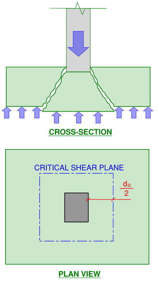
An isolated footing in its simplest form comprises a rectangular or square shaped concrete mass with bottom reinforcement supporting a single column or wall. This will be the focus of this article. The concepts explained here can then be expanded to assist in the analysis of isolated footings supporting multiple structural elements or other more complex arrangements. Lets now take a look at a cross-section view of this simple arrangement…
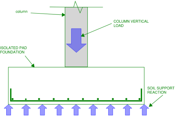
Load is applied to the footing via the column or wall it supports. The resultant reaction at the under-side of the footing is the bearing pressure from the soil. The responsibility of the isolated footing is to adequately spread the relatively concentrated load from the column/wall over an acceptable plan area of soil so that the bearing capacity of the soil is not exceeded.
This spreading action of the load over a larger area is achieved through the isolated pad undergoing bending and shear (as a horizontally spanning member)…
From this behaviour, we can determine that the isolated footing may fail in one or more of the following ways…
Soil Bearing Failure in an Isolated Footing
The first key failure in isolated pad footing design is bearing failure of the soil. This occurs when the applied pressure from the pad footing via the column/wall load exceeds the bearing pressure capacity of the soil. Reasons for this may include:
- Plan dimensions of the isolated footing are too small, therefore spreading the column/wall force over a small area thus increasing the applied pressure.
- The soil bearing capacity is too low
- The column/wall load is too high
- A combination of the reasons above.
Since you usually can’t change the column or wall load that the footing supports and you generally cant change the soil bearing capacity, the usual preventer of this failure is to ensure that you have provided enough contact area between the pad footing and the soil.
The allowable bearing capacity of the founding soil is provided by your friendly project Geotechnical Engineer. To ensure that your footing contact area is adequate, you simply perform the following check…
Where:
N* = Un-factored working load from the column or wall. Note that a little bit extra should be added on top to account for the self weight of the footing itself.
Note that this approach is not exactly a true to life representation of the stress distribution under an isolated footing. However this approach will be adequate for most standard footing designs. For a detailed look at how the real stress distribution exists under an isolated footing using the assistance of FEA analysis and soil spring stiffness, take a look at THIS article. The software I used for that article was RAM Concept.
One-way Shear Failure in an Isolated Footing
Once the plan area of the footing has been established, the next possible failure mechanism is through on-way shear.
One-way shear behaviour in an isolated footing is very similar to that of a concrete beam. Indeed, the approach to check one-way shear capacity for an isolated footing uses the same equations for shear capacity of a beam.
The critical shear face is calculated at a distance of do/2 from the face of the column which the footing supports. (do is the effective depth of the footing for shear and is the distance from the centroid of the tension reinforcement to the extreme compression fibre of the concrete)…
The equations to check for one-way shear capacity have changed quite a bit in the latest version of AS3600 (the Australian Concrete Design Code). For a very in-depth coverage of this, and a discussion on potentially a mistake which may exist in this section of the code, take a look at THIS article. For the purposes of this article, we will go through a summary of the equations used…
One-way Shear capacity of a concrete element is determined from the contribution of the shear capacity provided by the concrete added with the contribution of the shear capacity of the shear reinforcement.
For the application of an isolated footing, top reinforcement is generally not provided. In addition, to achieve an efficient design, shear ligatures should also be avoided. That is to say that the depth of your isolated footing should be proportioned such that the one-way shear demand on the footing is supported solely by the contribution from the concrete. For a fun article on whether or not top reinforcement is required in your isolated footing, have a read of THIS article.
Therefore we are only interested in the equations in AS3600 which are associated with the shear capacity of the concrete only. In addition to this, isolated footings generally do not have post-tensioning provided within them. Therefore the effects of post-tensioning within the formulas found in AS3600 can be equalled to zero.
The relevant chapter is 8.2. We won’t need to account for torsion within the footing so we start straight at equation 8.2.4.1…
Where:
Vuc = Shear Strength of Concrete
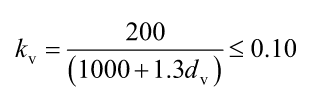
kv = Factor containing an allowance for strain in the concrete due to shear. At this stage I would recommended calculating this value using the simplified method found in Clause 8.2.4.3.
bv = Effective width for shear. For isolated footings, taken as the dimension perpendicular to the critical shear plane (full width of footing)
dv = Effective depth for shear. It is taken as the greater of 0.72D or 0.9d. D being the gross depth of the footing, and d being the distance from the centroid of the longitudinal tension reinforcement to the extreme compression fibre of the concrete.
f’c = Strength grade of concrete
For a footing with no shear reinforcement, the simplified method for calculating kv is found in clause 8.2.4.3 and looks like this…
Its then just a mater of inputting all your values in the the equations then solving. Don’t forget to add your safety reduction factor for final design. For shear with no shear reinforcement 0.7 should be adopted in accordance with table 2.2.2 of AS3600.
Punching Shear Failure in an Isolated Footing
Punching shear is another possible failure mechanism of an isolated footing. The key difference between punching shear and one-way shear is that the critical shear plane for punching is a perimeter around the supported column rather than a single plane…
The equations to calculate the punching shear capacity for a pad footing are different to that of one-way shear. For this, we need to head to the slab section of AS3600. The relevant chapter is 9.3.
Again, we ideally don’t want to be providing punching shear reinforcement for our pad footing. We will also keep it simple and assume that our column has a pinned base (therefore no moment transfer between column and pad footing). We therefore start with equation 9.3.3(1) in AS3600-2018, which looks something like this…
Where:
Vuo = Shear Capacity
u = Shear perimeter length around column or wall. Taken as the perimeter of the supported wall or column, extended a distance of do/2 away from all faces of the wall/column (as per previous image).
dom = The mean value of effective shear depth around the shear perimeter
fcv = An additional factor containing strength grade allowance and column footprint dimension allowance (see below).
Note that “σcp” is the average post-tensioning stress in the section. Because we don’t generally have post-tensioning in our isolated pad footings, this is set to zero so therefore is cancelled out. For a detailed article on what post-tensioning is and how it works, take a look at THIS link.
To calculate fcv you then use the following equation…
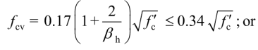
Where:
βh = Ratio of the longest dimension of the supported column or wall to the perpendicular dimension.
f’c = Strength grade of concrete as before.
Again, simply insert all the factors into the relevant equations and solve. Also like one-way shear, don’t forget to apply the safety reduction factor of 0.7 to your final punching shear capacity as well.
Bending Failure in an Isolated Footing
Bending is our lucky last possible failure mechanism for our isolated pad footing and therefore also needs to be checked.
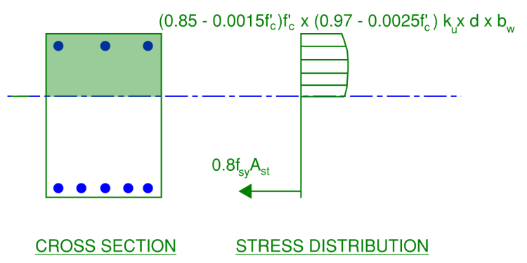
This is carried out using equilibrium of our cross-section and concrete stress block theory (just like we learned in university). There are some deemed to comply guidelines on the stress block assumptions in AS3600, these are included in clause 8.1.3…
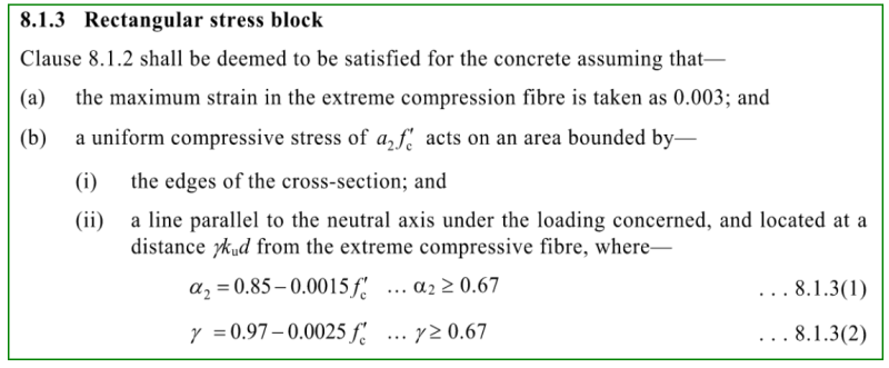
This means that your stress block analysis looks like the following arrangement…
You need to ensure that ku is less than 0.36 to ensure ductility in accordance with Clause 8.1.5 of AS3600-2018. Don’t forget to apply your safety reduction factor for bending of 0.85 in accordance with table 2.2.2 in AS3600 as well.
Isolated Footing Design Spreadsheet Calculator
Now that we know what the equations are and the philosophy of isolated footing design, here is a design spreadsheet to save time on your analysis. All user input cells are highlighted in yellow, all calculated output cells are highlighted in grey….
Isolated Footing Design Example (Full Working)
Here is a full worked example of a simple isolated footing design.
Assumptions and Summary:
- Allowable bearing capacity of soil is 350kPa
- Column is square 500x500mm
- Un-factored dead load is 1300kN
- Un-factored live load is 400kN
- Reinforcement cover is 50mm
- Reinforcement grade is 500MPa
- Concrete Grade is 50MPa
- Density of concrete is 25kN/m3
- Base of column is a pin (no moment transfer from column to pad footing)
Bearing Check
We will size our footing based on the allowable soil bearing of 350kPa. Our working load is…
1300 + 400 = 1700kN
Plan area of isolated footing is therefore…
1700 kN / 350 kPa = 4.86m2
Try a 2.4m x 2.4m footing…
2.4 x 2.4 = 5.76 m2 which is greater than 4.86m2 therefore OK. Additional area can account for self-weight of footing (currently not allowed for as depth yet to be determined)
Bending Check
First need to calculate ultimate load, so apply ultimate factors to dead and live loads. Lets assume a depth of footing of 600mm and include that in our loading as follows…
N* = (1.2 x 1300) + (1.5 x 400) + (1.2 x 2.4 x 2.4 x 0.6 x 25) = 2264kN
Turn this load into a stress so its easy to work with…
2264 kN / (2.4 x 2.4) = 393kPa
Critical design moment taken at face of column. Treat footing outstand as cantilever. Therefore cantilever span is…
(2.4/2) – (0.5/2) = 0.95m
Max moment (critical) assuming cantielver is therefore…
(393 x 2.4) x 0.952 / 2 = 426kNm
Check reinforcement requirements. Firstly effective depth (worse case is reinforcement in secondary layer, assume N20 bars used)…
d = 600 – 50 – 20 – 10 = 520mm
Use N20-300 bars.
Ast = (2400 / 300) x 314 = 2513mm2
Force in reinforcement at yield…
2513 x 500 = 1256500 kN
α2 = (0.85 – 0.0015×50) = 0.79
γ = (0.97 – 0.0025×50) = 0.87
ku = 1256500 / (0.79 x 50) / 2400 / 0.87 / 520 = 0.030
φM = 0.85 x 1256500 x 520 x (1 – 0.030 / 2) /1000000 = 548kNm greater than 422kNm therefore OK.
Shear Check
dv = maximum of (520 x 0.9) or (600 x 0.70) therefore = 468mm
V* = 390 x 2.4 (0.95 – 0.420/2) = 651kN
kv = 200/ (1000 +(1.3 x 468)) = 0.124
φV = 0.70 x 0.124 x 2400 x 468 x (min 500.5 or 8) = 691kN greater than 651kN therefore OK.
Punching Check
dom = 600 – 50 – 20 = 530mm
βh = 0.5 x 0.5 = 1
μ = (500 + 530) x 4 = 4120mm
fcv = 0.17 (1 + 2/1) x 500.5 = 3.61
φVu = 0.7 x 4120 x 530 x 3.61 = 5512kN greater than 2264kN therefore OK.
How do you compute the effective depth for bending for the secondary layer? I tried to recreate your spreadsheet but could not reproduce it using other data. Also the calculation for fcv seems wrong.