ETABS, developed by Computers and Structures Inc. is a powerful 3D finite element software for the design and analysis of buildings. It provides Structural Engineers with a powerful tool to model both simple and very complex structures. The user has the flexibility to design “stick” or “frame” elements (such as beams or columns). There is also ability to model shells or membranes for slab and wall elements. But what’s the difference between a shell vs. membrane element? and which one should you use in ETABS? Lets take a closer look…
By way of a summary, here is a table comparing the two area object types, membrane vs shell in ETABS…
| Membrane Slab | Shell Slab (thin-shell) |
| No out of plane bending stiffness | Out of plane bending stiffness considered |
| In plane bending stiffness considered | In plane bending stiffness considered |
| Distributes load to support beams/walls using tributary area algorithms | Uses the stiffness of the slab and the FEA analysis to distribute loads to support beams, walls or columns |
| Should not be used for two-way flat slabs | Can be used for two-way flat slabs |
| Can be used for one-way slabs | Can be used for one-way slabs only if bending stiffness modifiers are altered accordingly |
| Should only be used for slabs which are supported by beams or walls | Can be used for either slabs supported by beams and walls or self-supporting slab |
| Results do not give deflected shape | Results gives deflected shape |
Lets take a look at both now in more detail to help better explain this summary table…
(Do you enjoy using ETBAS? Would you like to learn more? Take a look at THIS article which explains a step-by-step process to modelling cracked shear wall behaviour in your ETABS model).
What is a Membrane in ETABS
A membrane in ETABS (and most other FEA software for that matter) is an area object which has no out-of-plane stiffness characteristics. That is to say, the theoretical bending stiffness of a membrane is zero.
A membrane element however has in plane stiffness and can transmit loading in its strong axis direction.
What is a Shell in ETABS
A shell in ETABS is an area object which has both in plane bending stiffness and out of plane bending stiffness.
Shell vs Membrane for Modelling of Slabs in ETABS
From the explanations above, you may be asking yourself “if a membrane has zero out of plane bending stiffness how can you model a slab? Isn’t a slabs primary function to transmit load to support columns through out of plane bending?”
This is a very good question. The fact is, you can model a slab using a membrane object in ETABS and it does “support” the loading just fine. When analysed, ETABS uses tributary area algorithms to transfer the load from a membrane slab directly to its supporting walls and beams. Note that a membrane will struggle to distribute load to support columns without beams and walls. Therefore it shouldn’t be used for an application such as a two-way flat slab.
Lets use a basic example to run a side-by-side comparison between a Shell vs Membrane slab in ETABS. We will set up a model for each with the following attributes:
- Squared Shaped slab 200mm (7.8 inch) thick. Two separate slabs will be used with exactly the same concrete grade and thickness. The only difference being that one will be defined as a shell, the other as a membrane.
- Four grid bays of columns in the x-axis and the y-axis all 8m (26.2 ft) apart.
- Supported by 600x600mm (23.6 x 23.6 inch) square columns, pinned at their top, fixed at their base
- No applied load to the slab, just a check on self-weight behaviour
Here is a plan view of what this looks like…
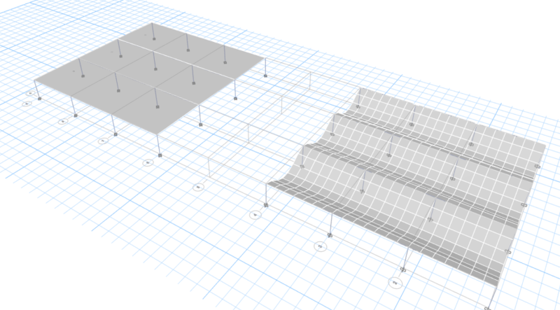
Lets take a look at the deflected shape perspective view for a membrane vs shell slab to compare their behaviour…
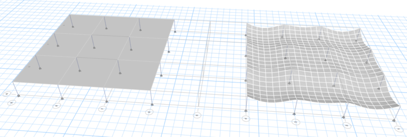
The membrane slab is on the left, the shell slab is on the right. The first thing you might notice is that it looks like our membrane slab is not deflecting at all. This observation is correct! Remember that the membrane slab doesn’t have any out-of-plane bending stiffness, so theoretically the deflection would be infinite!! Therefore there would be no logical way for ETABS to show this.
Instead, ETABS is using the tributary area load distribution to calculate the load allocation from the slab to the support columns. This lack of deflected shape is perhaps one downside of using a membrane to model your slabs. I personally use the deflected shape animations as a great checking tool to make sure my ETABS model is correct and properly defined. If you would like to find out how else I verify my ETABS models to make sure they are correct and not a “black box”, check out the article at THIS link.
The other thing you will notice is that the membrane slab on the left appears to not be “meshed”. This is because the auto-mesh function in ETABS automatically applies the “cookie cut” mesh option for floor membranes. This means that ETABS will automatically mesh the floor at support beams and walls.
Now lets take a look at the column base reactions for the self-weight in order to determine how the membrane slab is behaving…
Without even taking the calculator out, you can quickly see that the loading distribution is totally wrong!!
Without concerning ourselves with the magnitude of the loads, we can reasonably assume that all the corner reactions should be the same and this appears to be the case. However the remainder of the perimeter column reactions should also be the same. As we can see, this is definitely not the case. This is owing to the fact that the membrane slab works better when in conjunction with support beams or walls. For a two-way slab system, the membrane slab should not be used, but rather the shell option.
Here is a plan view of the column base reactions for the shell slab now…
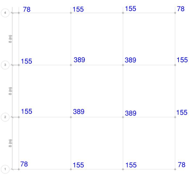
The shell slab load distribution looks much more logical. In all fairness to the membrane slab, it isn’t really recommended that it be used for a two-way slab application. However it does show how you can get terribly wrong answers if you don’t know what your doing with your FEA software!
Lets now add some 600×600 beams running in the up-down direction. This should be where the membrane slab give us accurate results. This time we will look at an animated screen capture of the dead load deflected shape…
We can see the same things pointed out earlier, the membrane slab on the left not meshing and also not showing a deflected shape.
With the introduction of the beams however, we can see that they are now providing support to the membrane and they are showing a deflected shape as expected. It is a little off-putting however seeing your slab behave like this if you are using a membrane (must admit personally I don’t like it very much when checking your floor for accuracy).
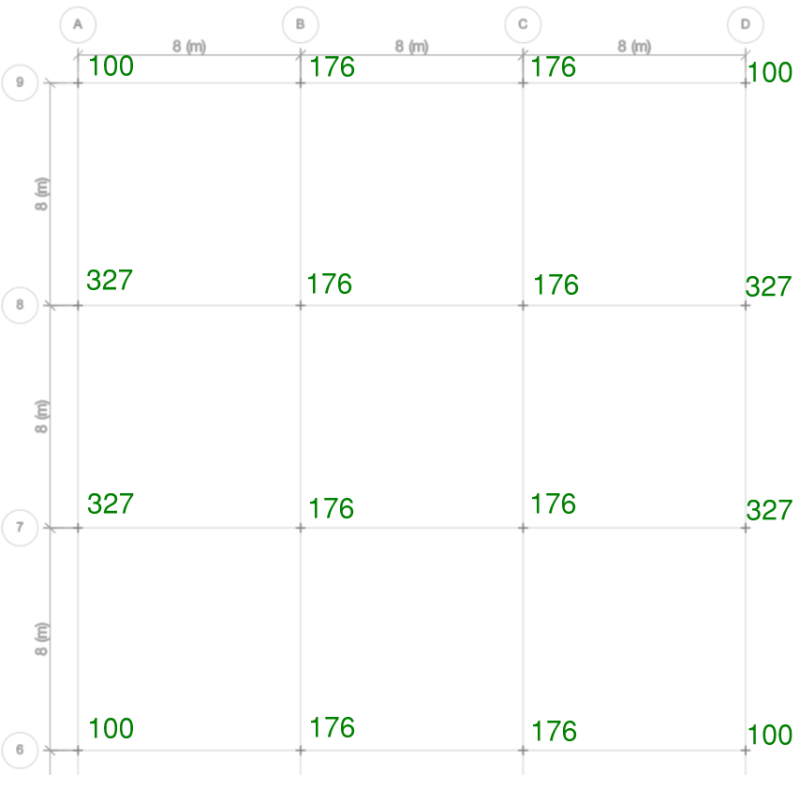
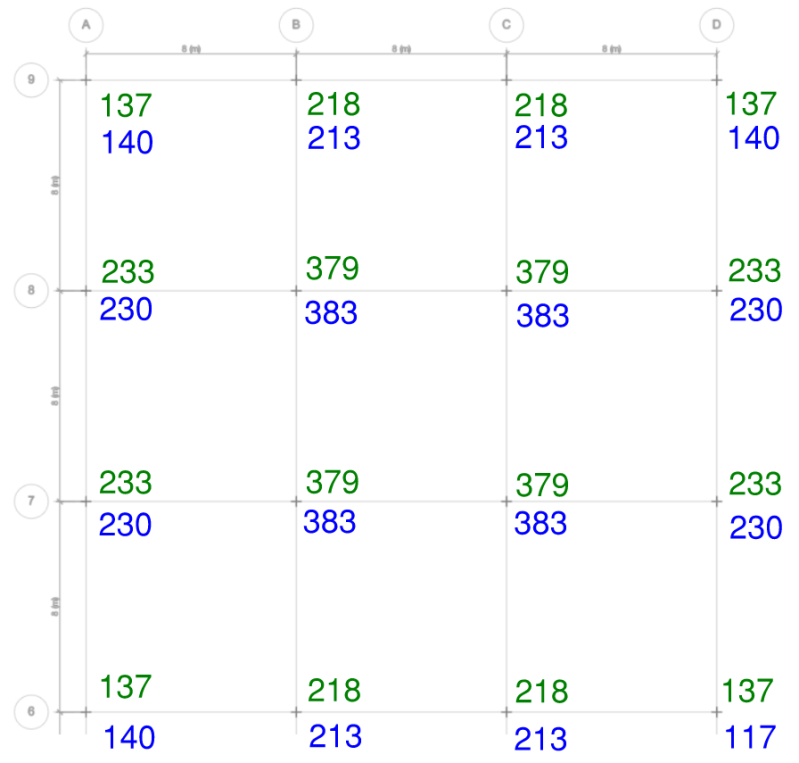
Lets now look at the column reactions again and unpack the results…
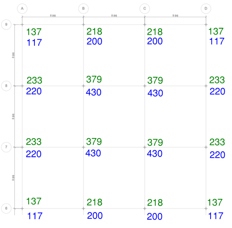
This time the results for dead load column reactions for both the membrane (green forces) and the shell (blue forces) are shown on the one plan above. In the plan above, the beams are running in the up-down direction. Here we can now see that the membrane slab is giving us results that look logical compared to our two-way slab trial.
We can also see that while the reactions for both the membrane and shell slabs are somewhat similar, they are still noticeably different. This is especially the case for the 4 interior columns on the floor plate.
The reason for this difference between the membrane vs shell slabs is that the membrane slab is now behaving like a pure one-way spanning slab. However the shell slab is applying some of its load to the support beams but it is also largely behaving like a two-way spanning slab.
Remember that the load distribution ETABS determines for a membrane applies the load directly to its support beams and walls. Therefore, with only beams running in the up-down direction on screen, the membrane slab load is being distributed 100% in the left-right direction.
We can test this theory by cracking our shell slab to have an infinitely small bending stiffness in the up-down direction (m11 axis in ETABS). Then we can compare our results which should be very close. First lets revisit the deflected shape for membrane vs shell slabs…
We can see now that the deflection behaviour of the shell slab on the right is looking much more like a one-way spanning slab (which is what we want!).
Lets now take a look at the column reaction comparison…
We can see now that the reactions are close enough to say that they are basically the same.
This would indicate that a membrane slab is best suited for a one-way slab system. Or a system where you have a slab supported by beams or walls.
If you feel like it however, you can always modify the stiffness factors of your shell slab to achieve a similar one-way behaviour if you desired as tested out above.
Additional Reading
If you found this article useful and enjoy using ETABS as part of your day-to-day Structural Engineering life, you may also find these articles interesting:
- HOW TO CHECK IF YOUR ETABS MODEL IS CORRECT – Sheer Force Engineering
- STRUCTURE IS UNSTABLE OR ILL-CONDITIONED: ETABS WARNING FIX – Sheer Force Engineering
- MODELLING CRACKED SHEAR WALL BEHAVIOUR IN ETABS – Sheer Force Engineering
- ETABS oAPI/API TUTORIAL: HOW TO CRACK AUTOMATION SPEED SECRETS USING VBA AND EXCEL – Sheer Force Engineering
- HOW TO SET UP GRIDS IN ETABS – Sheer Force Engineering