Not all basement walls are created equal. There are a number of engineering details and construction techniques which suite different applications and constraints for your project. In this article we will explore 5 different types of basement wall construction and compare them based on:
- Waterproofing Ability
- Buildability
- Usability
- Cost
Not only that, we will also take a deep dive into each basement wall type and explore different elements that make up each one as well as the construction methodology of how they are put together.
Basements can be constructed either using top down or bottom up methods. This article will focus on the conventional bottom up methodology. If you would like to learn more about top down construction of basements take a look at the article at THIS link.
So lets quite literally stick our heads in the sand and dig a little deeper into the different types of basement wall construction methods and wall types…
What is a Basement Anyway?
A basement is a floor or entire structure which is partially of fully imbedded below natural ground level. This requires that the external walls of the floor or structure need to perform one or more of the following jobs:
- Retain soil (keep soil out of the building)
- Provide waterproofing (keep water out of the building)
- Support the vertical load of the structure itself if it has upper floor levels.
There are a range of basement wall construction techniques, selection of the best one for your project is dependant upon:
- The soil conditions of your site: Is the soil cohesive (clayey) or non-cohesive (gravel/sand), is very high strength rock present.
- How deep your basement needs to be: Is it a single level basement for a residential application or a multi-level basement car park for a high-rise office building.
- Weather you basement is above or below the water table: Is your lowest basement level significantly lower than the expected water table level of the area? Is the basement close to the shoreline?
- Proximity of the basement to site boundary or neighbouring structure: Does a structure exist close by which may run the risk of being undermined depending on the basement wall construction type chosen?
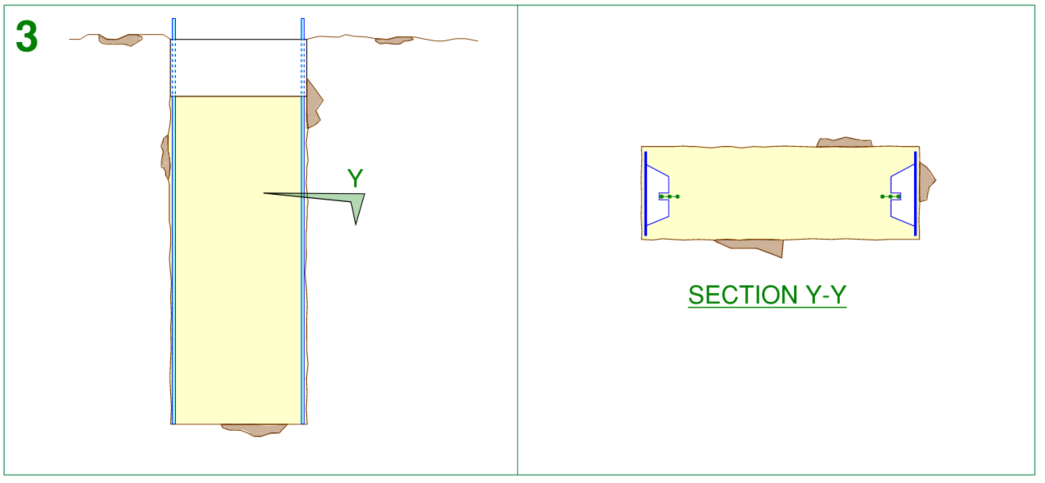
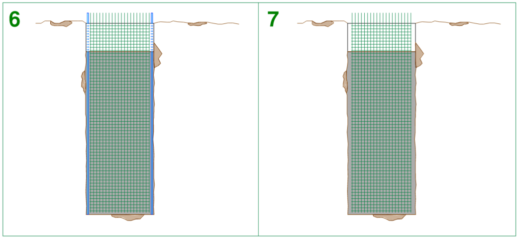
Flat Profile Basement Wall
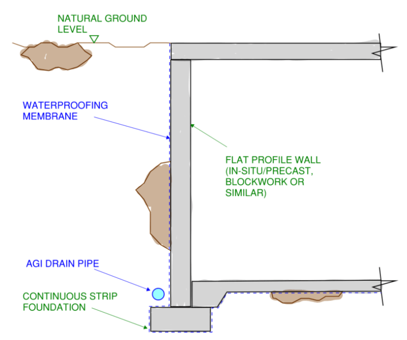
A flat profile wall generally comprises a continuous strip foundation supporting a flat profile wall constructed of either concrete, blockwork or other proprietary wall systems such as Dincel or AFS.
Waterproofing Measures for Flat Profile Basement Walls
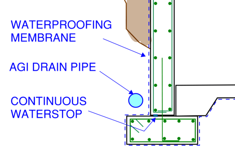
The flat profile basement wall offers quite a number of options for waterproofing measures. Because access can be achieved to the back of the wall during construction, a full waterproofing membrane can be applied and also lapped with the damp proof membrane located beneath the basement slab. This creates a continuous waterproofing barrier to prevent water entering the basement.
If a concrete wall is use, the only real cold joint is located between the top of the continuous strip foundation and the base of the wall. The engineer and builder may choose to provide an additional layer of insurance for waterproofing by providing a continuous bentonite waterstop along this junction.
Prior to backfilling the outside of the wall with soil, a continuous agricultural drainage pipe (often referred to as an Agi Drain), can be installed which provides further protection against water entering the basement by relieving any possible build-up of water pressure to the back of the wall.
Due to the many options for layers of defence against water entering your basement, the flat profile basement wall performs very well under the waterproofing metric.
Waterproofing Ability = Very Good
Groundwater can impose significant force on basement structures through what is called hydrostatic pressure. The presence of hydrostatic pressure can influence the effectiveness of a basement walls waterproofing ability. To learn more about hydrostatic pressure and how it relates to basement structures, take a look at THIS article.
Construction Methodology of Flat Profile Basement Walls
The construction methodology of a flat profile basement wall is relatively straight-forward, so much so that this is a very common wall type in the residential sector.
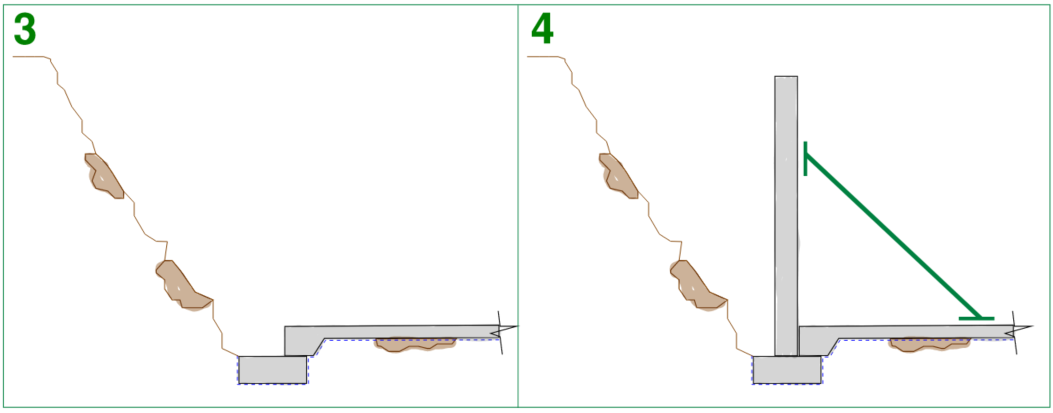
- Complete bulk excavation of basement (requiring a temporary batter around the basement perimeter) and detailed excavation of continuous strip foundation, then lay damp proof membrane
- Construct continuous strip foundation
- Construct basement slab
- Construct flat profile wall and prop back to basement slab
- Construct basement “lid” (usually the ground floor slab)
- Install Agi drain and back fill excavation adjacent to the wall with granular drainable material.
The flat profile basement wall is readily constructible. No specialist trades, labour or machinery is required and if structural blockwork is chosen, manual handling of materials can be used for sites which may have restricted access or cranage limitations.
It must be noted that due to the requirement of a temporary batter to be provided around the perimeter of the basement during construction, this basement wall type cannot be used if the basement is in close proximity to the site boundary or a neighbouring structure.
Due to the relative straightforward nature of construction the flat profile basement wall is a standout for buildability.
Buildability Score = Very Good
Usability of Flat Profile Basement Walls
The flat profile basement wall falls a little short on the usability front. As mentioned above, this wall type cannot be constructed directly against a site boundary or neighbouring building.
Further to this, there are limitations to how deep the basement can be constructed. For projects that require multiple levels of basement construction (2-3 basement levels or more) it begins to become non-feasible to introduce significantly large temporary batters which take up a lot of room on the site. Temporary props are also then required to penetrate intermediate basement levels which begins to cause site coordination and access issues.
For these reasons, this wall type does not perform as well as the later examples explored in this article for usability.
Usability Score = Average
The Wonderful World of Piles
The next three basement wall types are constructed with piles being the primary structural element, so we need to understand a little about piles to put things into perspective.
A pile in construction terms is a sub-structural element resembling the form of a structural column which makes up the structures foundation support system or basement wall construction system.
Piles can be constructed from poured in place concrete, pre-cast concrete, timber or steel.
Have you ever wondered how Structural Engineers verify that the final constructed pile is strong enough to support the design loading? Take a look at THIS article which covers the different types of pile testing.
The two main types of piles used in basement wall construction are Rotary Bored Piles (often referred to as simply Bored Piles) and Continuous Flight Auger Piles (also referred to as CFA Piles or simply CFAs). Both of these pile types utilise circular reinforced concrete construction. The main distinction between CFAs and Bored Piles is how they are constructed.
What is a Rotary Bored Pile?
A bored piling rig uses a drill bit which comprises a short steel helical cutting blade attached to a rotating shaft. The piled hole is constructed by progressively screwing the cutting blade into the soil then removing the blade from the excavated hole along with the cut soil where it is placed in a truck as spoil and taken from site. This process is repeated until the excavated hole reaches the required design depth.
Once the excavation is completed, the reinforcing cage is placed inside and the concrete is then placed using the tremie method.
The tremie method of placing concrete involves lowering a pipe to the base of the excavation, the pipe end at the top of the excavation is connected to a concrete hopper. The hoper and the pipe are then charge with the wet concrete mix. The pipe is then slowly lifted out of the excavated hole, placing concrete as it goes. During the lifting process, concrete is continuously replenished to the hopper in order to keep the system fully charged.
Bored piles are great for almost all soil types and have less restriction on depth (deeper piles can be achieve through simply lengthening the drill shaft). Because larger depths can be achieved, bored piles are ideal for supporting heavy loads.
The drilling method however generates more vibration and noise compared to CFA piling.
Because the excavated hole is reliant upon the soil being self supporting in the temporary case during construction to prevent it from caving in, bored piles are not suitable for soil conditions which comprise deep gravely or sandy soils and to a lesser extent locations where the pile is requried to extend below the water table.
What is a CFA Pile (Continuous Flight Auger)
A CFA piling rig uses a drill bit which comprises a long steel helical cutting blade which runs the full length of its drill shaft. The drill shaft is a hollow tube through which concrete can be pumped.
The pile is constructed by first using the cutting blade to penetrate the soil to the required design depth (in this case, the spoil is not removed progressively but left in the hole). As the full length helical blade is retracted from the hole, it takes the soil along with it, while at the same time placing concrete as it rises out of the excavation.
Once the drill bit is removed from the hole, the reinforcement caged is plunged into the still wet concrete.
CFA piles are less suited to penetrating rock and, due to the drill bit configuration, the depth of pile is restricted. For this reason CFA piles are not as effective in supporting heavy vertical loads.
The CFA construction methodology allows the walls of the excavation to be stable at all times during construction with support being provided by either the yet to be removed spoil or the wet concrete mix. This makes the CFA pile ideal for deep gravely and sandy soils as well as applications where the pile is require to extend beneath the water table.
What’s the Difference Between CFA Piles and Bored Piles?
In summary, the differences for both a CFA Pile and a Bored Pile are best illustrated with a comparison table…
| CFA Piles | Bored Piles | |
| Drill Bit Used | Short steel helical bit | Full length helical bit |
| Available Depths | Up to 29m (95 foot) | Up to 80m+ (262 foot) |
| Available Diameter | Up to 1.2m (4 foot) | Up to 2.4m (7.5 foot) |
| Suitability for Rock | Less Suitable | More Suitable |
| Suitability for Deep Gravel/Sand | More Suitable | Less Suitable |
| Suitability below Water table | More Suitable | Less Suitable |
| Concrete Placement Method | Tremie | Through drill shaft |
| Suitability to support large vertical loads | Less Suitable | More Suitable |
| Noise/Vibration | Less Noise/Vibration | More Noise/Vibration |
These two pile types only scratch the surface of the different possible types of piles and pile foundations. To learn much more about different pile foundation types and their benefits take a look at THIS article.
Now that we know a thing or two about circular reinforced concrete piles lets take a look at the next three basement wall construction types.
Soldier Pile Basement Wall
The soldier pile basement wall comprises concrete piles spaced at regular intervals. Between the piles shotcrete infill panel walls are constructed which span horizontally between the piles. Finally a continuous capping beam is provided to tie all of the structural elements together.
For further reading on how solider pile retaining walls can fail, take a look at THIS article for details.
Waterproofing Measures of Soldier Pile Basement Walls
Options are a little more restricted with a solider pile wall when it comes to waterproofing. Because access cannot be gained to the back of the piles during construction due to the presence of dirt, an applied waterproofing membrane cannot be effectively used.
The junction between every soldier pile and its corresponding shotcrete infill wall results in an obvious cold joint at multiple locations which must be treated for waterproofing. Here a continuous bentonite waterstop can be used, however it is not usually the best only line of defence you should use to keep water out of your basement.
For this reason, the soldier pile retaining wall is best used for projects where the basement lies above the water table level.
There are some opportunity for waterproofing measures to be applied however in order to keep moisture out when above the water table. In addition to a waterstop between each cold joint, a continuous vertical strip drain can be installed to the back of the shotcrete infill panels during construction. These strip drawings run down to an Agi drain which runs around the perimeter of the basement, this goes a long way in relieving any possible water pressure build-up on the back of the wall.
Due to the constraints surrounding this wall types waterproofing capability, the solider pile wall type has the following ranking…
Waterproofing Ability = Average
Construction Methodology of Soldier Pile Basement Walls
Construction of a soldier pile wall requires the assistance of a piling rig. This is a reason why it is mainly seen on commercial basements and larger apartment type developments as the costs associated with construction is somewhat higher than a conventional flat profile basement wall.
- Piles are constructed using a piling rig. Once a full run of piles are constructed, the capping beam is formed into the soil and constructed to tie the piles together.
- The shotcrete and strip drain are installed in stages. The length of each stage is dependant on the soil conditions, for cohesive soils this length can be up to 1.5m for sandy soils this length is reduced. Firstly a localised excavation adjacent to the wall is performed then the strip drain is pinned to the soil face and shotcrete is applied to the soil face to construct the infill wall panel.
- Depending on the depth of the basement and the allowable length of the shotcrete segments, step 2 is repeated until the shotcrete wall reaches the required level at the bottom of the basement slab. For deep basements of more than 3m, temporary ground anchors may be required to keep the wall stable until the internal basement slabs and ground floor slab is completed, the ground anchors are usually drilled through the piles and into the dirt at regular vertical intervals.
- Once the shotcrete infill wall has reached its required depth, the bulk excavation for the basement is completed and the strip drain is connected to the perimeter Agi pipe.
- The damp proof membrane beneath the basement slab is then laid proof membrane and construct the basement slab.
- The basement “lid” is then constructed (usually the ground floor slab)
This basement construction type requires the assistance of a piling rig and specialised equipment for the shotcrete infill panels. The specialised nature of this equipment is dependant on the local industry you are in. Solider pile basement walls are widely used in my hometown of Melbourne, if you park in a multi level basement car park, chances are you may see this detailing (although it is common practice to construct a secondary non-structural wall immediately in front of this type of basement wall as the concrete finish on the piles is usually quite… industrial).
Buildability Score = Good
Usability of Solider Pile Basement Walls
Soldier pile walls can be constructed directly adjacent to your site boundary and/or a neighbouring building. Provided lateral movement is controlled in your design, you can quite comfortably retain a multi level existing building adjacent to your basement!
Soldier pile wall construction is also restricted mostly to soil conditions which have a certain degree of cohesion. For the temporary case during construction, this method relies on the soil being self supporting prior to the shotcrete infill being constructed. For this reason, a soldier pile wall would not be suitable within very sandy soil types.
In terms of depth, the sky is the limit (or should it be the reverse of that?) , you are only restricted by the piling rigs available in your region (and therefore maximum pile diameter/depth), cost and in the case of the shortcomings of the water proofing ability of this wall type, the location of your water table.
Usability Score = Average
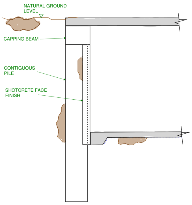
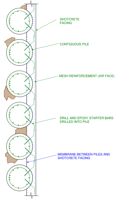
Contiguous Pile Basement Wall
A contiguous pile basement wall is similar to the soldier pile retaining wall in that it comprises a series of piles at regular intervals. However the main difference is these piles are much closer together (distance can range from 150mm clear gap between pile or in some cases the piles almost touching).
Similar to the soldier pile wall, a shotcrete wall is then constructed, however it is less structural and more aesthetic in this case as the shotcrete is more of a facing finish rather than a spanning element between the piles.
Waterproofing Measures of Contiguous Pile Basement Wall
Due to the very close spacing of the piles, there is limited access ability to the dirt face during construction to place an applied membrane for waterproofing.
This means that the majority of the waterproofing membrane lies between the piles and the shotcrete facing. This it not ideal considering that drill and epoxy starter bar reinforcement tying the shotcrete to the piles penetrates the membrane at numerous locations which causes potential locations for leakage.
Since the integrity of the applied waterproofing membrane is compromised by drill and epoxy starter bar reinforcement, the contiguous pile wall scores a little lower in the waterproofing ranking…
Waterproofing Ability = Good
Construction Methodology of Contiguous Pile Basement Walls
The construction methodology of a contiguous pile wall is the same for a soldier pile wall, the only difference being that there are more piles and at closer spacing.
Therefore, in terms of constructability, there isn’t much difference between the two, however the contiguous pile wall ranks slightly lower due to the larger quantum of piles required and therefore increase construction time and materials requirement.
Buildability Score = Average
Usability of Contiguous Pile Basement Wall
Similarly with the soldier pile wall, the contiguous pile wall has no real depth constraints aside from piling rig availability and ability to go down to depth.
Unlike the soldier pile wall however, the contiguous pile wall is great for soil conditions which are very sandy and low cohesion. This makes it ideal for almost all types.
While waterproofing measures are available, the requirement to have a significant amount of drill and epoxy reinforcement penetrating the waterproofing membrane means that while this wall system can be used below water table, if the basement is significantly far beneath the water table, it begins to be a non-feasible wall type.
The contiguous pile wall can also be constructed directly adjacent to a site boundary or neighbouring structure provided that the lateral movements of the wall are controlled within the design.
Usability Score = Good
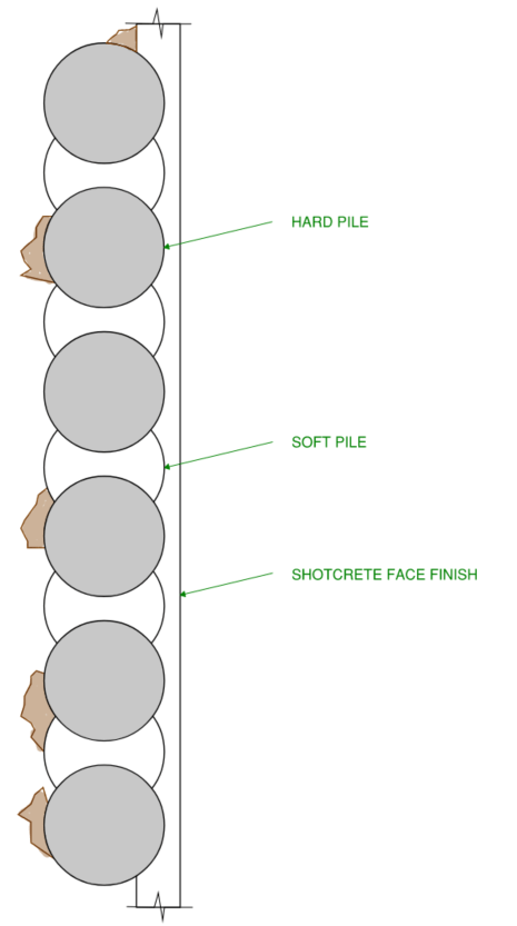
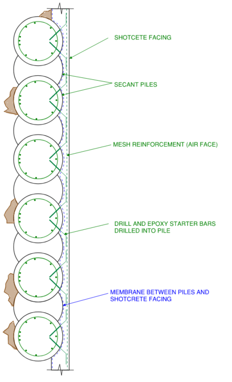
Secant Pile Basement Wall
A secant pile basement wall is comprised of a series of piles at regular intervals which are very closely spaced. The spacing is so small that the piles overlap one another.
To achieve this, a secant pile wall is constructed of alternating pile types:
- Hard Piles: Usually are reinforced with a conventional reinforcement cage or an imbedded structural steel member and is constructed with high strength grade concrete.
- Soft Piles: An un-reinforced pile constructed of low strength grade concrete.
The piles are constructed in a hit-mis fashion, that is the soft piles are constructed first, followed by the hard piles. The piling rig is required to chew through the soft piles during the construction of the hard piles, this forms an interlocking detail between the hard and soft piles with assist with strength and waterproofing.
Finally, after the piles are completed, the secant pile wall is usually finished with a shotcrete face to assist with waterproofing and the overall visual appearance of the wall.
A cross section view of a secant pile wall looks almost identical to the contiguous pile wall due to its arrangement, the image below shows a plan view of the secant piling arrangement.
Waterproofing Measures of Secant Pile Basement Wall
The interlocking nature of the hard-soft pile arrangement in secant walls gives it great inherent waterproofing capabilities in its own right.
Coupling this with a waterproofing membrane for added assurance against water finding its way through the wall, the secant pile wall is a great system for overall waterproofing.
For its fantastic waterproofing characteristics, the the secant pile wall scores very highly on this metric…
Waterproofing Ability = Very Good
Construction Methodology of Secant Pile Basement Walls
The construction methodology for a secant pile wall is very similar to that of the soldier pile wall and the contiguous pile wall. The main difference being that the secant pile wall is constructed in a hit-miss sequence, that is that the soft piles are constructed fist along a row, then the construction team return to complete the hard piles between each one.
- Soft piles are constructed using a piling rig.
- Hard piles are constructed using a piling rig.
- Once a full run of piles are constructed, the capping beam is formed into the soil and constructed to tie the piles together.
- The basement is fully excavated to the required design level.
- The shotcrete wall face is applied to the hard and soft piles.
The sequencing requirement of the secant pile wall does make it a little trickier to build. Also the concrete mix properties need to be correct because if the soft piles achieve much higher strength than required, the piling rig may struggle to chew through the pile edges when it comes time to install the hard piles. For this reason the secant pile wall type is a little more specialised.
Adding to this the matter that this wall type requires a lot of piling… and I mean a lot! The construction time can be quite drawn out.
For these reasons, the secant pile wall receives the following constructability ranking…
Buildability Score = Poor
Usability of Secant Pile Basement Walls
The secant pile wall can be used in multiple different soil types due to its non-reliance on the soil being self-supporting during temporary construction stages. It can also remain effective when deep below the water table and has limited restrictions around depth requirements
Usability Score = Very Good
Diaphragm Basement Wall (or D-Wall)
Our final basement wall type is the Diaphragm wall (also known as a D-Wall).
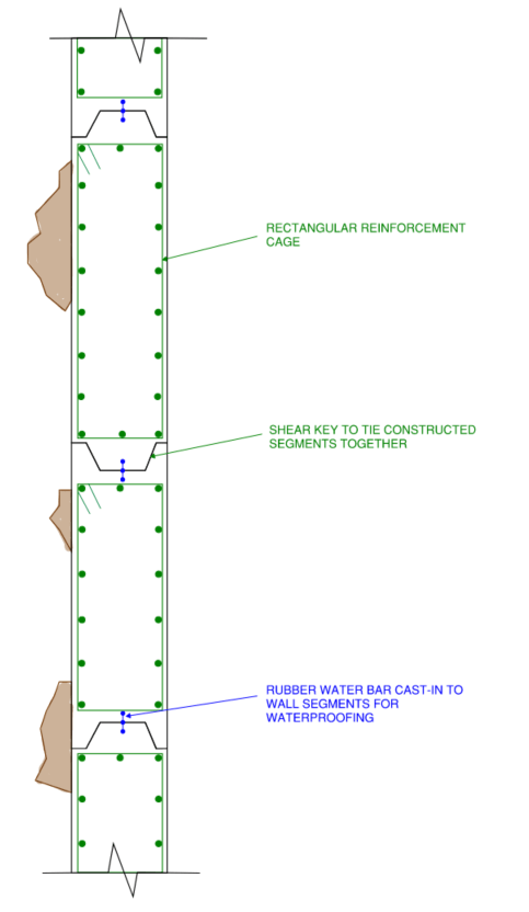
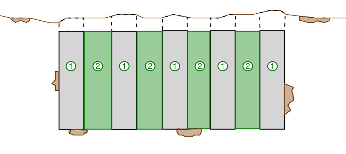
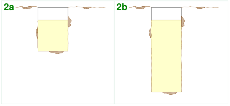
A diaphragm wall is a rectangular profiled reinforced concrete wall constructed in segments usually around 6m in length (or 19.5 foot). The segments interlock through shear key connections to form a continuous rigid wall once all of the segments are completed. It is constructed by excavating rectangular trenches in an alternating pattern using a different type of rig compared with a bored pile or a CFA pile.
Waterproofing Measures of Diaphragm Basement Walls
As part of the construction of each segment, a steel shutter is placed at either end which forms the shear key and also contains a continuous rubber water bar. Once the segment is completed, the steel shutters are removed however the rubber water remains cast-in to the concrete. Once the adjacent wall segment is constructed against this face the opposing side of the water bar is then cast-in to that adjacent wall panel.
The interlocking nature of the shear keys coupled with the cast-in water bar makes the diaphragm wall extremely good at waterproofing basements which are below the water table.
The detailing of the diaphragm wall makes it the best performer for waterproofing giving it the following ranking…
Waterproofing Ability = Very Good
Construction Methodology of Diaphragm Basement Walls
The diaphragm basement wall is usually constructed in segments with length of around 6m each. The segments are constructed in a hit-miss fashion, this means that one 6m segment is constructed (or 19.5 foot), followed by a 6m gap, then another 6m segment is constructed. Once the second 6m gap is constructed the 6m gap between the two segments is filled in. This process is continued for the required full length of the basement wall.
The following construction sequence outlines the construction methodology for a single 6m long diaphragm wall panel segment.
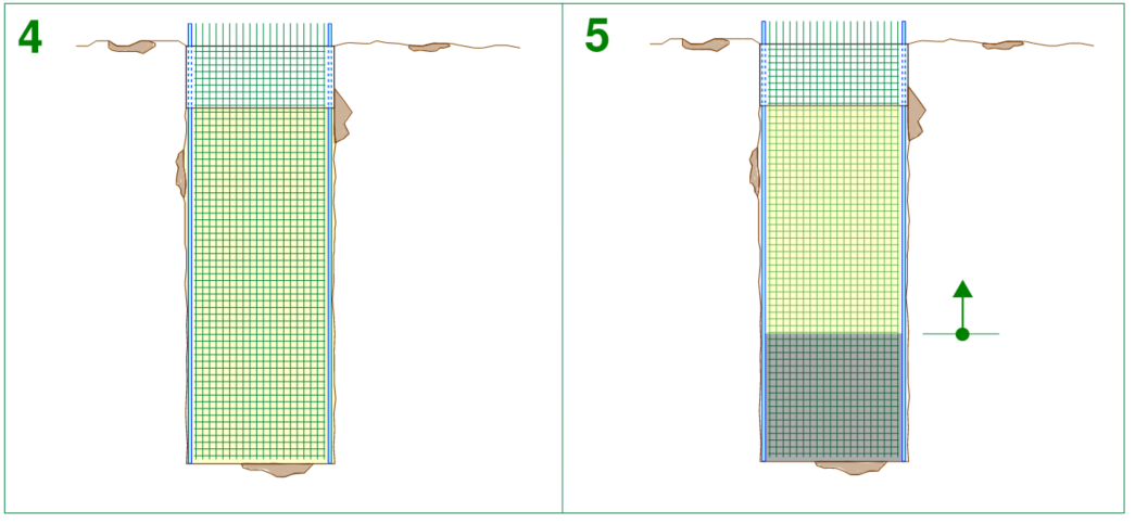
- A reinforced concrete guide wall is constructed at the first 1 to 1.5m depth of excavation. The purposes of this wall is to ensure that the excavation equipment for the deeper portion of the dig remains within acceptable tolerances to make the wall as true and square as possible.
- A grabber bucket is used to excavate the wall in segments. While the grabber is pulling soil out of the hole, bentonite mud is pumped into the hole to keep it full. The bentonite mud mixture is usually mixed and batched with a mini plant on-site. The bentonite mud is a relatively runny mixture whose duty is to ensure that the walls of the excavation remain stable and don’t collapse into the excavated trench.
- Once the trench is dug to the requirement basement level, steel stop-end shutters are installed at the trench ends. The steel shutters are profiled so that a key is formed into the side of the diaphragm wall segment, allowing for an interlocking connection to the construction of subsequent segments. A rubber insert (water bar) is also usually provided for added waterproofing capabilities.
- The reinforcement cage is lowered into the completed trench
- Concrete is then placed into the trench using the tremie method. Tremie placement of concrete involves lowering a pipe to the base of the trench, the pipe at the top of the trench is connected to a concrete hopper. The hopper and the pipe are then charged with the wet concrete mix. The pipe is then slowly lifted out of the excavated trench, placing concrete as it goes. During the lifting process, concrete is continuously replenished to the hopper in order to keep the system fully charged.
- Concrete placement continues and as the concrete is placed it displaces the lighter bentonite mud mixture upwards. To prevent the excavation from overflowing with bentonite mud, the bentonite is pumped away by a separate extraction bump while the concrete is being placed.
- After the concrete is set, the steel end shutters are removed and the construction team move to the next wall segment location to repeat steps 1 through to 7 again.
The site coordination and specialised equipment required for a D-wall makes it one of the more complex basement wall types to construct. The following key points effect the D-walls ranking for the buildability category:
- Requirement for a mini plant for preparing and batching the bentonite mud mixture which may take up valuable construction site space.
- Slow excavation process for digging the trenches
- Multiple pump requirements operating at the one time (concrete pump and bentonite extraction pump) also taking up more space on the construction site and requiring coordination between the two.
Buildability Score = Poor
Usability of Diaphragms Basement Walls
Diaphragm walls can be constructed at significant depths. The grabber attachment of the excavating rig can be replaced with rock cutting attachments which allows the D-wall to be used in a wide range of soil conditions.
The geometry of the wall and the ability for large quantities of reinforcement means that the D-wall can retain significantly large surcharge loads.
The one downside for usability of the D-wall is the requirement for multiple pumps and mixing plants which may take up valuable site space especially for construction sites that have limited room for temporary plant equipment.
Usability Score = Good
Summary
OK, that was a lot of information to take in across a lot of different comparison metrics.
Lets summarise everything into a nice digestible comparison table. The following table outlines the 5 different basement wall types we explored in this article with their corresponding ranking score for each metric.
| Waterproofing Ability | Buildability | Usability | Cost | |
| Flat profile Wall | Very Good | Very Good | Average | Very Good |
| Soldier Pile Wall | Average | Good | Average | Good |
| Contiguous Pile Wall | Good | Average | Good | Average |
| Secant Pile Wall | Very Good | Poor | Very Good | Poor |
| Diaphragm Wall (D-Wall) | Very Good | Poor | Good | Poor |
Conclusions
Structural Engineers, contractors and architects have a lot of choice when it comes to basement wall construction types, each one having their own pros and cons.
While this study has been a comparison between 5 different wall types in a general sense, the goal of the design team is to choose the appropriate wall system whose strengths and weaknesses are complemented by the unique challenges of the specific project site.
Some sites may pose challenges such that certain basement wall types are simply not feasible, this is the beauty of the art of structural engineering, the answer is not always clear and in some cases there may be several answers to the same question.
What has your experience been with basement wall design and construction? What are some of the local construction techniques used in your region? Feel free to leave a comment below to take the discussion further.
7 thoughts on “BASEMENT WALL CONSTRUCTION METHODS: WHICH ONE IS BEST FOR YOUR PROJECT?”