Water is a wonder of nature. It is essential to our survival. A running stream can be incredibly relaxing. However a dripping tap in your house can be irritating. It is used as a source of fun in the summer time with pools and water-pistols, yet unwanted water in your home or building can be devastating. The forces of water on buildings can have significant impacts to the structures performance. Force excreted by a liquid is referred to as hydrostatic pressure. This article takes a deep dive into hydrostatic pressure and how it relates to buildings with basement structures…
The hydrostatic pressure of a liquid is the pressure exerted by that liquid at rest due to the forces of gravity. Generally the hydrostatic pressure within a liquid increases with depth. Basement structures constructed below the water table are susceptible to hydrostatic pressures. The hydrostatic pressure in basement structures are supported by the basement walls and a hydrostatic slab.
What is Hydrostatic Pressure
As outlined in this articles summary, hydrostatic pressure is the pressure excreted by a liquid at rest and is caused by gravity acting upon the liquid.
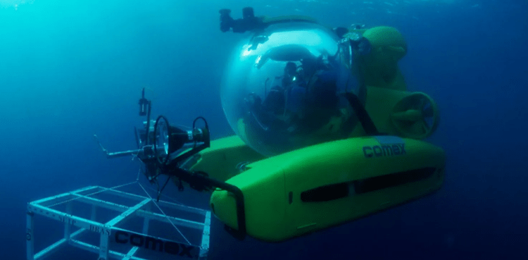
This is best seen in the depths of the ocean. In deep sea exploration, you will often see specialised submarines which are designed to withstand significant pressure. This is because, the deeper you are under water, the higher the hydrostatic pressure.
The formula to determine hydrostatic pressure applied to an object is as follows…
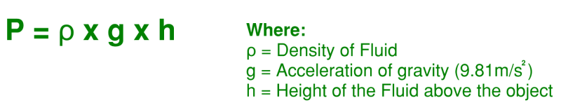
The first term is the Greek letter Rho (Ï) and is a measure of the fluids density. Density is often expressed in terms of kilograms per cubic metre or pounds per cubic foot (for more on density as well as densities of common construction materials, take a look at THIS article). Using this equation we can say that:
- Increasing a liquids density will increase the hydrostatic pressure. It is generally accepted that the density of water can be taken as 1,00kg/m3 as a nice round number.
- Increasing the gravity will increase the hydrostatic pressure (for all intents and purposes this factor remains a constant on planet earth however handy to know that all things being equal, we will experience 2.4 times the hydrostatic pressure on Jupiter compared to earth, Source)
- Increasing the liquids depth will increase the hydrostatic pressure (as mentioned above, the deeper you are below sea level, the higher the pressure experienced).
Where can Hydrostatic Pressure be Found in Buildings
Hydrostatic pressure in buildings is found wherever a building element is required to directly support a liquid.
A very visual example of this is a suspended slab supporting a swimming pool. You can see this in most inner city “luxury” apartments complexes or hotel facilities.
However a less obvious and more interesting example is hydrostatic pressure applied to basement structures within buildings (if you would like to learn more about basement wall construction in buildings, take a look at THIS article).
A basement is a floor or an entire structure which is partially or fully embedded below natural ground level. Because basements lie beneath natural ground level, there are occasions where the basement level is lower than the regions water table. This is dependant on the depth of the basement and the location of the sites water table level.
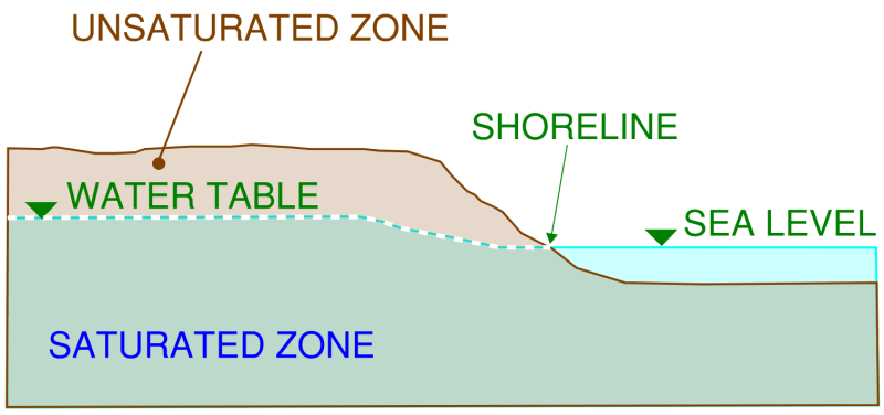
A water table is the boundary between fully saturated and unsaturated soil zones. Above the water table (in the unsaturated zone) the voids between soil particles are filled with air. Bellow the water table (the saturated zone) the voids between the soil particles and rock gaps are filled with water.
The water which fills the voids between soil particles and rock fractures is called “groundwater”. Groundwater can find its way into the soil through rain and subsequent seepage of the rain through the soil depth. Or through water flow through an aquifer.
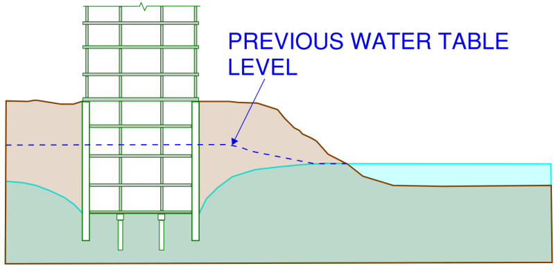
Lets take a look at a schematic cross section through a coastal shoreline where the land meets the ocean. It is common to find a shallow water table close to the shore, here is what this arrangement may look like…
Now lets take this same arrangement and build a high-rise apartment building with associated multi-level basement car park structure. We can then start to appreciate the hydrostatic pressures which are involved…

Here we can apply what we have now learned about hydrostatic pressure to help us understand the forces now acting upon the basement structure.
- Basement Walls: The hydrostatic pressure starts from zero at the water table level (where saturated and unsaturated zones meet) and increases linearly to a maximum at the lowest basement level. From our understanding of the hydrostatic equation, the density of water and acceleration of gravity are constant with the only variable being height (or in this case depth).
- Hydrostatic Slab: The hydrostatic slab supports a constant upwards pressure. Again referring to the hydrostatic pressure equation, now all three components of the equation are constant; density of water, acceleration due to gravity and depth. The constant upwards pressure is equivalent to the maximum horizontal hydrostatic pressure experienced by the basement walls at the very base of the walls.
The upwards hydrostatic pressure experienced by the hydrostatic slab is an interesting phenomenon. It is best visualised with an experiment. Taking an empty cup and pushing it into a water container with the cups opening facing upwards is a very good analogy to the pressures experienced by the basement example illustrated above. You will notice that the deeper you push the cup into the water, the more resistance and upward force you will experience (this is the hydrostatic pressure increasing with an increase in depth)…
How to Relieve Hydrostatic Pressure from a Basement
Basement structures broadly sit within two separate categories:
- Drained Basement: Is a basement structure which has sub-soil drainage systems provided under the basement slab and/or behind the basement walls. This effectively drains the groundwater away and relieves the hydrostatic pressure from the structure
- Undrained Basement: Is a basement structure which has no sub-soil drainage provided. This means that the water pressure is allowed to build up against the structural elements of the basement
So a drained basement is one which relieves the hydrostatic pressure from groundwater. Lets take a look at some detailing to achieve this…
Agricultural Drains (or Agi Drain) to Relieve Water Pressure
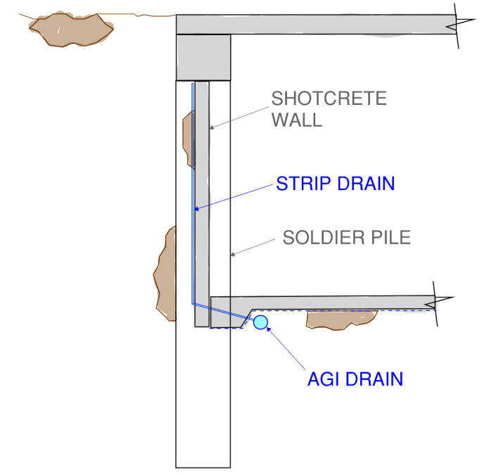
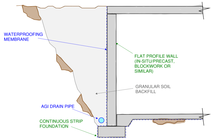
The most common way to relieve water pressure from basements caused by groundwater is the agricultural drain, or Agi Drain. The Agi drain is usually placed at the lowest point of the basement wall to allow gravity to channel the water towards it. The soil immediately around the Agi drain is usually replaced with crushed rock, sand or other well draining back-fill. This assists with helping the water drain away.
The series of agricultural drains usually run to a central sump pump for collection. This then allows the groundwater to be pumped into the sewer system and away from the building.
Here are two examples of basement walls which use Agi drains to help relieve the water pressure placed upon them…
French Drains to Relieve Water Pressure from Basements
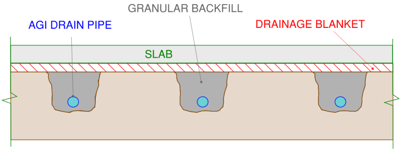
A series of French drains connected by a continuous drainage layer is often used beneath the slab of a basement. This helps to relieve the upward pressure on the basement slab caused by the groundwater.
A similar principle applies to under-slab drainage as with basement wall drainage. A series of Agi pips run beneath the slab and are placed in trenches which are then back-filled with granular backfill. The slab is then poured above a continuous drainage blanket. A drainage blanket usually comprises an outer “sock” with pores small enough to prevent soil from entering the inside of the blanket yet large enough to allow water to pass through. The interior of the blanket is usually a grid mesh of plastic which prevents the blanket from being crushed and allows the water to freely flow and drain away from the slab…
Sometimes you Can’t Relieve Hydrostatic Pressure from a Basement
Sometimes you simply can’t relieve the hydrostatic pressure on a basement for a number of reasons:
- The groundwater may be contaminated, requiring it to be treated prior to being pumped into the sewer system, this may be non-feasible and/or costly.
- Excessive drainage of groundwater may lower the water table level under adjacent buildings and structures. If these structures lie above reactive clays, this may cause subsidence of the foundations and damage to the neighbouring buildings.
- Your local council may prohibit groundwater from being pumped into the public sewer or wastewater systems.
- There simply might be too much volume of groundwater to pump away from the building. This may mean that it is not feasible to have pumps large enough and with enough volume to adequately relieve the hydrostatic pressure rom the basement walls and slab.
Lets looks at our original example of the multi-level basement car park constructed close to the shoreline. However, this time, lets assume we have now introduced drainage measures making this a drained basement and therefore relieve the hydrostatic pressure on the basement structure…
Here we see something interesting happening to the water table level compared to what it was previously. Due to the introduction of the basements drainage system the water table level has been lowered considerably from where it was before. The water table level may tend to return back to its original level some distance away from the building. The distance being dependant on the drainage characteristics of the soil and the flow rate of the groundwater.
This effect is called groundwater drawdown (and looks somewhat like the effect you would see from taking the plug out of a drain pipe). In this specific example we can now see that relieving the hydrostatic pressure from the basement wall and slab may not be feasible because:
- There is a seemingly never ending supply of groundwater re-entering the basement envelope due to the adjacent ocean. This may mean that the sump pump system is required to run continuously day and night for the life of the building. Even with back-up pumps this may be both costly and not feasible.
- Depending on the depth and plan area of the basement, a significantly large volume of water may need to be continuously pumped away from the building. There may not be pumps with sufficient capacity to handle the volume.
- The pumped water is most likely highly saline (salty) due to the adjacent ocean. Most councils will require that the salt and other contaminants be removed prior to the water being pumped away from the building. Depending on the contaminants involved, a mini water treatment plant may need to be constructed within the basement to treat the water. This can become extremely costly and require ongoing maintenance and running costs.
- The groundwater drawdown effect next to the basement may have adverse affects on the neighbouring buildings. This can result in costly lawsuits due to damages caused to these structures.
For instances where it is not feasible to provide drainage to a basement to relieve the hydrostatic pressure, things start to get a little more extreme from a Structural Engineering perspective. This means that the basement structure is required to withstand the hydrostatic pressure directly.
Lets take a look now at how basement structures withstand the strong forces of ground water on a real example project…
How Basements Support the forces of Hydrostatic Pressure with a real life Example
The basement structure itself is the first line of defence for groundwater trying to find its way into a building. From the empty cup test explored earlier in this article, we can see that for a basement constructed beneath the water table, water is trying to force its way in at every direction.
Lets take a look at a real project I’m currently working on which is located in the Melbourne CBD. The proposed building is quite a unique structure, it comprises:
- 4x multi-level basement intended for mass storage.
- 2x Above Ground Levels
- Water table level 8.7m below natural ground level (or 28.5 ft)
- Total depth of basement 19.5m (or 64 ft)
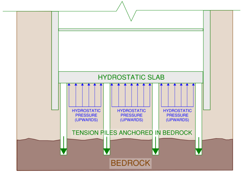
Here is an isolated cross-section sketch view of this arrangement focusing on the basement zone…
From this arrangement we can see that the difference in level between the water table and the bottom of the basement is 19.5 – 8.7 = 10.8m (or 35.4 ft). This is the “height” or depth portion of the hydrostatic pressure equation we covered earlier (this can also be referred at as the hydraulic head). We can determine the theoretical maximum upward hydrostatic pressure on the base slab assuming acceleration of gravity to be 9.81m/s2 and the density of water to be 1,000 kg/m3 …
Hydrostatic Pressure = 10.8 x 1,000 x 9.81 = 106,000 N/m2 or 106kPa
This is an extreme pressure for a slab to handle. To put things into perspective, here are some dot points to help understand how large 106kPa (or kilopascal) is…
- Loading dock slabs designed to support truck loading are rated to 12kPa
- The density of Concrete is 25kN/m3 meaning that a concrete slab thicker than 8 metres is required to counteract the upward hydrostatic pressure
- The self-weight of an 11 storey concrete building produces an average pressure of 106kPa across its footprint!!!
With only 6 suspended floors of concrete structure holding it down, this example buildings basement will simply pop out of the ground due to buoyancy effects generated by the hydrostatic pressure. So something needs to be introduced to anchor the building down…
For this example, an 800mm thick hydrostatic slab (31.5 inch) has been adopted. This gives about 20kPa of downwards pressure due to the self-weight of the slab to counteract the uplift caused by hydrostatic pressure. Often, when the water table is closer to the bottom of the basement, the dead weight of the hydrostatic slab alone is enough to anchor things down. However on this occasion the shortfall of 86kPa is taken up by tension piles anchoring the hydrostatic slab and therefore the structure down to bedrock.
2 thoughts on “WHAT IS HYDROSTATIC PRESSURE IN BASEMENT STRUCTURES”