Lateral torsional buckling (LTB) in beams is a phenomenon that all Structural Engineers should understand. From what it is, what causes it and how to prevent it (for a list of other things Structural Engineers should know take a look at the article at THIS link). If you are a Structural Engineer and don’t know what lateral torsional buckling is (shame on you!) fear not this article covers everything you need to know in relation to lateral torsional buckling, so lets dive head first…
Lateral torsional buckling is a phenomenon which occurs in un-restrained beams which have undergone bending. The internal compression and tension forces generated within the cross section as a result of the bending contribute to this form of buckling. The compression half of the cross section tends to buckle in a lateral direction, while the tension half tends to remain closer to the un-deformed location due to the restorative effects of the tension within it. The combined effects of the behaviour between the compression and tension portions of the cross section results in a rotational and lateral displacement of the overall beam. Open sections and deep narrow sections bending about their major axis are more susceptible to lateral torsional buckling due to their low capacity against buckling in the horizontal direction under compression forces.
The Engineering Behind Lateral Torsional Buckling
To begin with, we are going to look at simple bending theory of beams. You will see this used A LOT on Sheer Force Engineering. This is for good reason, simple bending behaviour can explain a lot of structural behaviour of elements within buildings…
A simply supported beam spanning between two supports when loaded will undergo bending. The bending will tend to stretch the bottom portion of the beam and compress the top portion. In short, the internal forces which resist bending within a beam is a coupling of tension and compression. Lets take a look at a simple diagram of this arrangement (this is the arrangement we will be using to explain lateral torsional buckling in this article)…
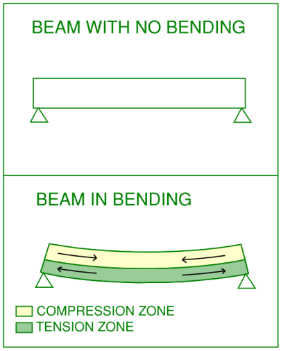
This can also be visualised using a household sponge and introducing bending into it. The compressible nature of the sponge allows you to visualise what is happening in a structural beam when it is bending. In the image below, vertical lines are drawing on the sponge so you can see how the bending planes behave in relation to each other..

Here is a list of articles on Sheer Force Engineering which use this behaviour to explain other structural concepts:
- How bending works in post-tensioned slabs and how post tensioning improves bending performance
- Is top reinforcement required in isolated footings?
- How to design a truss quickly using simple hand calculations
- Why do concrete beams crack, and how to identify structural cracks
Now we have re-capped bending behaviour in beams, lateral torsional buckling can be readily understood…
Behaviour of the Top half of the Beam During Lateral Torsional Buckling
With the top portion of our beam in compression, this behaviour resembles that of a column. When a member undergoes compression, a couple of things may happen (or a combination of the two)…
- The member shortens due to the compression. At lower load levels the member may spring back when un-loaded (if it is operating within its elastic range). At very high load levels the material may fail/yield in compression (an indicator of this is that it will not spring back once the load is released).
- The member may buckle. At lower load levels the buckle may come out if the load is removed, at higher load levels the member may buckle so much that yielding can occur (resulting in the buckle not coming out when the load is removed).
Buckling behaviour can be demonstrated if you take a plastic ruler and compress it with your hands from each end. Because the ruler is slender in one direction, this is the direction in which it will tend to buckle as shown here…

Behaviour of the Bottom Half of the Beam During Lateral Torsional Buckling
Now we move to the bottom portion of the beam. We know that the bottom portion of the beam undergoes tension during bending.
There is an interesting behaviour of a member which is in tension. For this analogy we will use the case of a guitar string. Guitar strings are tensioned to achieve the desired pitch. The tension in the guitar strings creates a restorative force within it. If you pluck a guitar string it will vibrate and eventually return to its original position (for more on this, take a look at THIS article about vibration analysis of slabs). If you pull the guitar string sideways and let it go gradually, it also tends to return to its original position. Here is a little demonstration…
Combined Behaviour of the Top and Bottom portions of the beam during Lateral Torsional Buckling.
These two behaviours of compression and tension in the respective top and bottom portions of the beam is what can cause lateral torsional buckling.
Lets now take our example beam arrangement and assume that the beam in question is an “i” beam (universal beam). If we assume it to be simply supported and loaded on its top flange it will bend. Say we load it up substantially enough to generate lateral rotational buckling, here is the mechanics of that process:
- The top flange undergoes compression and begins to buckle horizontally. The horizontal buckling occurs because this is the weak direction of buckling and the path of least resistance to buckling failure. The beam will not buckle vertically as the depth of the overall beam is effectively restraining it against buckling in that direction.
- The bottom flange undergoes tension. The tension in the bottom flange provides restorative force on the bottom half of the beam which tends to keep it closer to the un-deformed location.
- The buckling of the top flange laterally begins to pull on the bottom flange in the same direction, however the restorative tension force in the bottom flange prevents this from occurring.
- The coupling effect of the top flange buckling horizontally and the bottom flange remaining relatively in its same location produces torsion in the beam (rotation) as well as a lateral displacement (hence lateral torsional buckling)…
How Lateral Torsional Buckling Affects a Beams Strength
Depending on the beams aspect ratio and its un-restrained length, LTB can significantly reduce a beams bending capacity.
In most cases, lateral torsional buckling occurs at bending moments much less than what the section would have otherwise been capable of supporting.
Lets take a 610UB101 for example (this is an “i” beam 610mm deep, 24 inch). Varying only the effective un-restrained length, we can see the effects on its bending capacity…
How to Prevent Lateral Torsional Buckling in Beams
There are a number of measures Structural Engineers can put into place to prevent and reduce the effects of lateral torsional buckling in beam designs. Lets take a look at each one and how to apply them…
Restraining the Compression Zone of the Beam
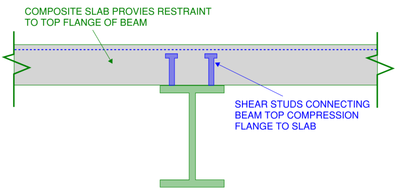
The most effective way to prevent lateral torsional buckling is to provide restraint to the compression zone of the beam.
An example of this is the connection of the top flange of a beam as part of a composite steel floor system. Here, the introduction of shear studs on the top flange imbedded into the concrete slab effectively restrains the top flange from buckling…
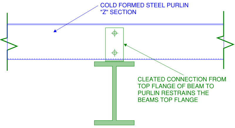
In a steel shed or warehouse structure, the steel rafters usually support a series of secondary purlin members. The top flange connection to these purlin members also act as a good restraining element to the compression flange of the rafter (in the downward load case)…
Timber beams are equally susceptible to LTB. In a timber example, the floor joists of your house are most likely restrained by the timber flooring that it supports. This acts as a good restraining element against lateral torsional buckling…
Applying the load to the Tension Zone of the Beam
The location at which the load is applied to the beam can have a significant effect on how it performs against lateral torsional buckling.
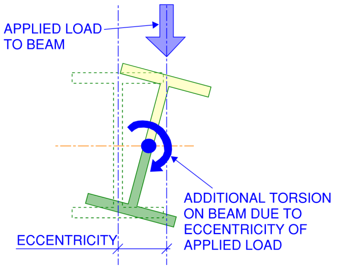
The most onerous location to apply a load to a beam in terms of lateral torsional buckling is the compression flange. Although it is sometimes impossible to avoid it, applying the load to the tension half of the beam improves its buckling performance.
This is because once the buckling begins to occur, the vertical load, coupled with the eccentricity which is generated through the lateral displacement results in the applied load contributing to the effects of lateral torsional buckling…
Support Condition of the Beam
The support condition of the beam can influence its performance for LTB.
Pinned connections such as simple cleat plates provide little rotational restraint so therefore don’t enhance the beams performance for this type of buckling.
Fully fixed end connections such as bolted end plates, and fully welded connections provide good torsional restraint and therefore increase the beams performance for this form of buckling.
Member Selection to Prevent Lateral Torsional Buckling
The cross section of the beam can directly influence how it behaves for lateral torsional buckling.
Members which perform very well under this form of buckling include:
- Closed sections (such as rectangles, squares and circular hollow sections)
- Wide cross-sections (due to large capacity against lateral buckling)
- Flat cross-sections
Final Thoughts
Lateral torsional buckling makes up a very big portion of structural steel design and to a lesser extent timber design. It is extremely important that Structural Engineers understand its principles, what causes it and how to prevent it.
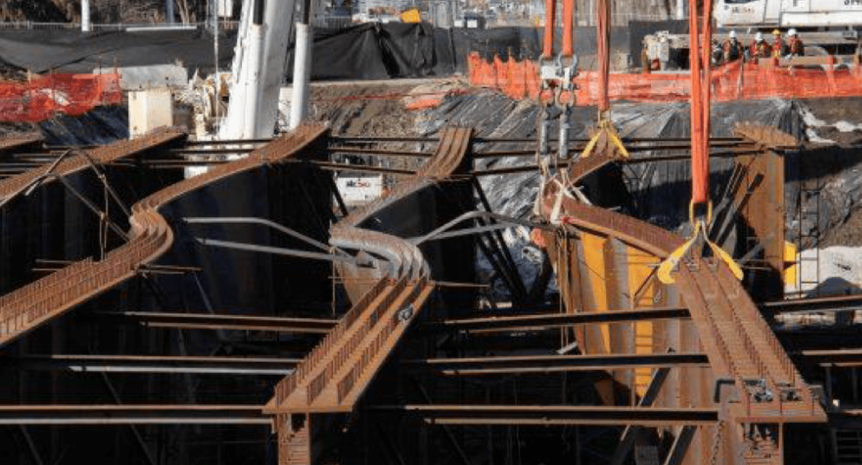
The phenomenon is most common during construction when at the various stages not all parts of the structure are tied together and completed. A bridge which was being demolished in Mexico failed due to lateral torsional buckling of its steel girders as the restraining concrete deck was being removed. Take a look at the news article at THIS link.
After having gone through all of that theory, lets take a look at a real life test example where a beam is proportioned and loaded to force lateral torsional buckling to occur.
The featured image of this article was sourced from www.mdpi.com