In steel construction of sheds and warehouse buildings, there is a small element which has a huge impact on the overall performance of the building and its members. The aptly named fly brace can drastically improve a beam or columns performance due to its restraining characteristics. So what is a fly brace and what does a fly brace do? This article answers both…
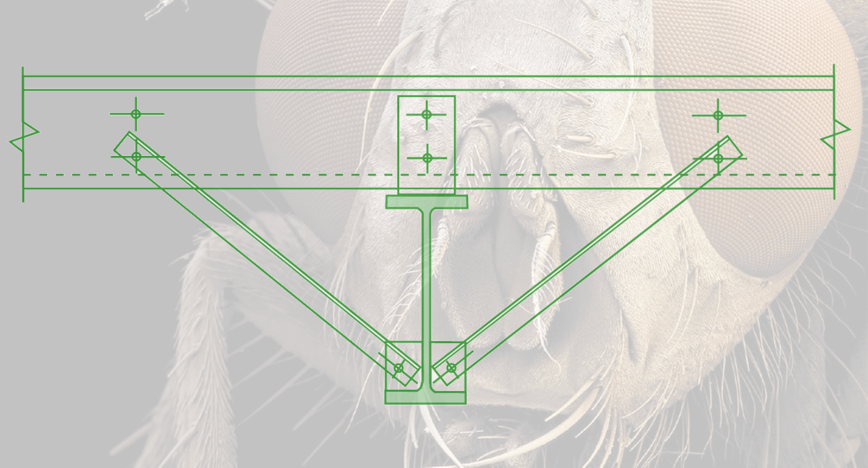
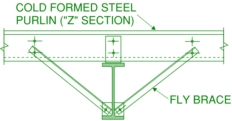
A fly brace in construction terms is a short diagonal member, either a strap or angle section, connecting to an otherwise un-restrained flange of a spanning beam or column. The structural purpose of a fly brace is to restrain the member it attaches to against the phenomenon of lateral torsional buckling. This form of buckling is a twist or torsional response a member undergoes due to bending.
To understand exactly how a fly brace works, we need to understand the phenomenon of lateral torsional buckling…
The Fly Brace and Lateral Torsional Buckling
I strongly recommend that you first read THIS article which covers everything you need to know about lateral torsional buckling, what causes it, and how to prevent it so that you can fully grasp what a fly braces purpose is.
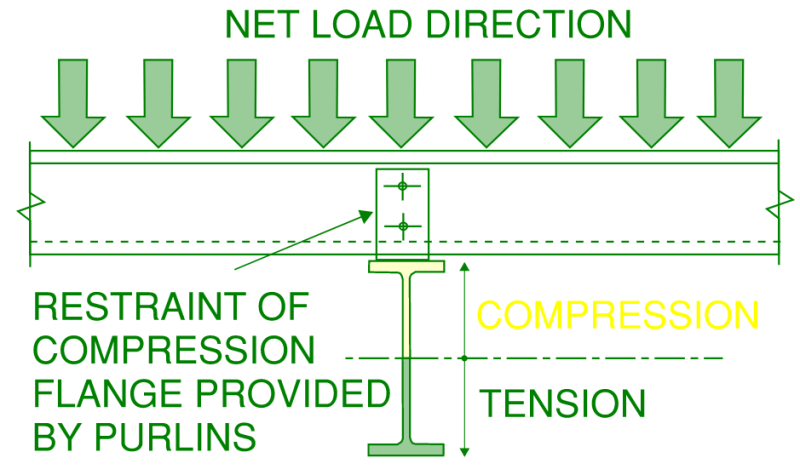
By way of quick explanation, lateral torsional buckling occurs in members which undergo bending. Beams develop internal coupling compression/tension forces as they bend. In the case of a steel rafter in a warehouse, under self-weight conditions, the top flange is in compression and the bottom flange in tension. Without restraint, the compression flange (top flange) tends to buckle horizontally which causes this form of torsional buckling…
Example Warehouse Application
Lets dig a little deeper at this example “i” section rafter mentioned above. In the self-weight and dead/live load condition, the top flange is in compression and is effectively restrained by the purlins that is supports…
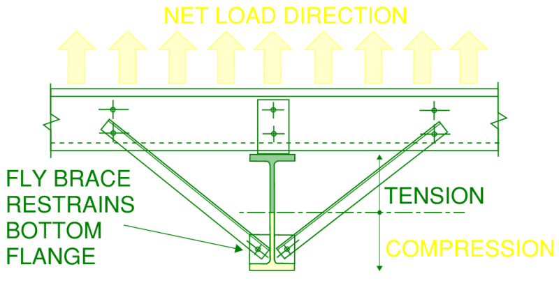
In lightweight steel construction such as large warehouses and sheds however, the wind loading on the roof can generate a net up-lift and therefore an upward force on the steel rafter. This can result in a reversal of the internal forces. In this situation the bottom flange can undergo compression and the top flange tension. This can result in a very long un-restrained length for the bottom flange which can result in failure via lateral torsional buckling. The introduction of the fly brace provides this necessary restraint to prevent this buckling from occurring…

Without the fly braces restraining the bottom flange the rafter may need to be significantly increased in size to prevent it from buckling. It is generally a cheaper option to provide the fly braces in lieu of increasing the rafter size. The graph below shows the bending capacity of a 610UB101 (an “i” beam 610 mm deep or 24 inches), for varying un-restrained lengths. This shows how effective fly braces can be in adding strength to spanning members…