It was one of the worst industrial disasters in the History of Victoria Australia. The ripple effect of this event changed construction and bridge design globally in the early 1970’s. This event was the collapse of the West Gate Bridge in Melbourne Australia. Following this disaster there were a lot of valuable lessons learned in the construction and engineering industries. Lets take a closer look as we ask… why did the West Gate Bridge collapse?
If you find forensic engineering interesting and want to learn more about past tragic engineering failures, take a look at THIS similar article which covers the structural reasons for the FIU pedestrian collapse in Florida.
For those who just want answers (spoiler alert)… the exact cause of the West Gate Bridge collapse is as follows…
Several factors caused the West Gate Bridge collapse. In summary the proposed construction technique required that the steel box girders be constructed in two separate halves at ground level then structurally connected once on top of their support piers. This required exact construction tolerances for each half to allow their connection to be successfully performed (a fact which the builder was apparently unaware of). Subsequent rectification works due to the misalignment of the box girder halves through a combination of jacking, loading and unscrewing of connection bolts all resulted in one of the spans becoming overstressed, causing its collapse.
In order to understand the collapse of the West Gate Bridge and its causes, we need to first understand the structural details and how it was proposed to be constructed, so lets start here first…
West Gate Bridge Structure Summary
The West Gate Bridge comprises two construction types. A concrete viaduct comprising concrete post-tensioned box girders which provides the approach ramping structure either side of the Yarra River and a 5 span steel box girder arrangement which spans across the Yarra River itself.
The collapse occurred within the extent of the steel box girder section, so the construction type and methodology for this portion will be the focus of this article (for more information on what post tensioning is and how it works, take a look at THIS article if you’re interested).
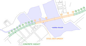
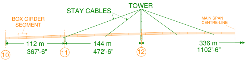
The numbering in the image above represents the support pier numbers. Each span is identified by the piers between which it spans. The details of the spans immediately above the Yarra River are as follows:
- Span 10-11: Simply supported span 112m (367′-6″) long
- Span 11-12: Back span support for main adjacent span over the river with one stay cable located at mid-span. Total length of span 144m (472′-6″)
- Span 12-13: Main cable stayed span over the Yarra River with total span of 336m (1102′-6″). Total of 4 support cable locations provided.
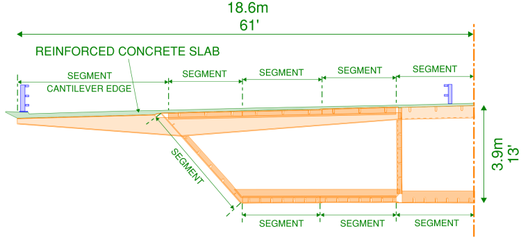
The elevation below shows a summary of this arrangement. For clarity, half the arrangement is shown with the other half being a mirror image about the main span centre-line.
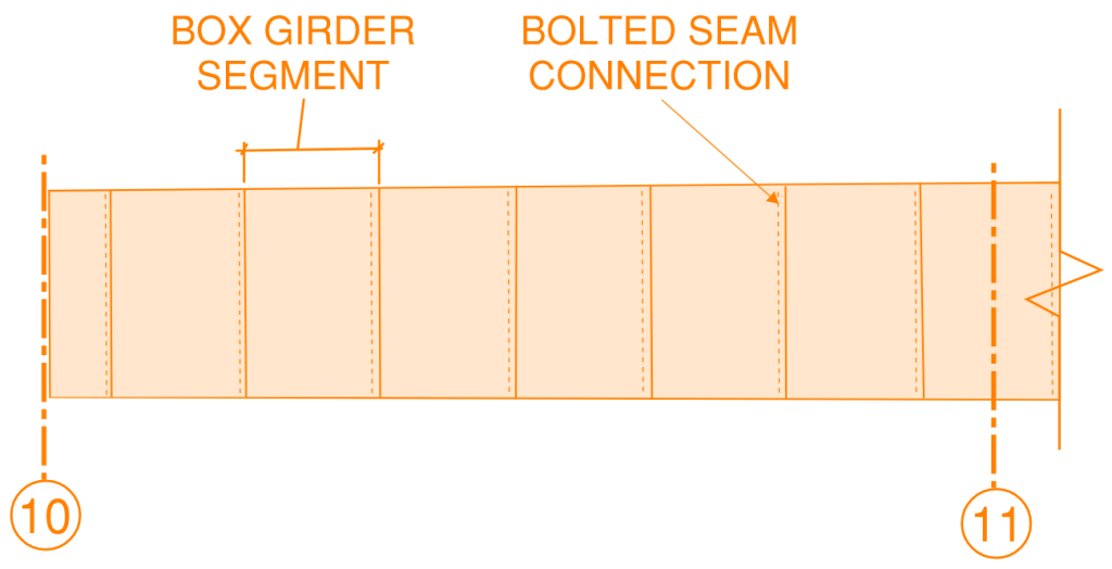
The main spanning girders were a trapezoidal steel box section. Due to the length of the spans and the size of the girders, each span was constructed in segments which were pieced together end-on-end. The connections of each section were a bolted seam type arrangement.
The cross-section of the trapezoidal box itself was also constructed in segments due to the sheer size of the girder. The overall dimensions of the trapezoidal box girders were as follows:
- 18.6m (61′) Wide (including the edge cantilever section)
- 3.9m (13′) Deep
The image below indicates the overall dimensions of the steel box girders as well as the break up arrangement of the panel segments from which it was constructed.
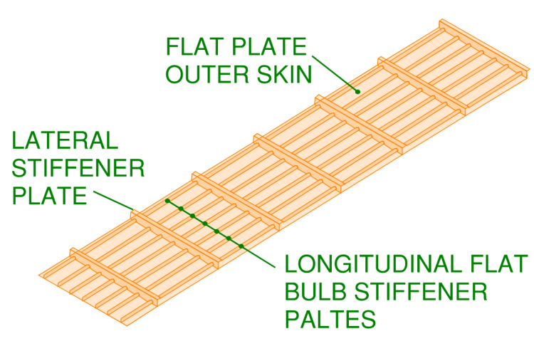
Each panel segment which made up the box girder comprised:
- Steel flat plate (the outer skin)
- Longitudinal fin plates to control the outer skin from buckling. These fin plates had a “bulb” on their inside edge which provided additional buckling stiffness.
- Lateral stiffener plates to control buckling.
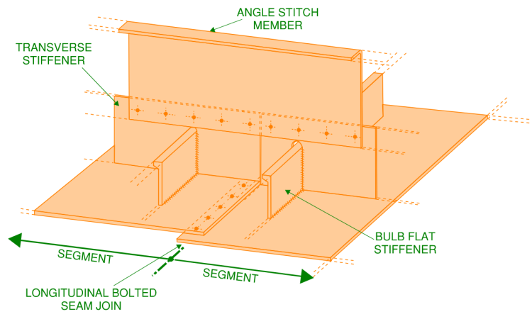
The box girder form was constructed by bolting these panel segment pieces together side-by-side. This resulted in several longitudinal seam joints between the segments. The lateral stiffeners for each segment were also tied together with a angle stitch member which was continuously bolted to the top of the transverse stiffeners.
For future reference in this article, the box girder contained the following elements:
- Inner bottom flange
- Outer Bottom Flange
- Inner Web
- Outer Web
- Outer Top Flange
- Inner Top Flange
- Cantilever/outrigger beams
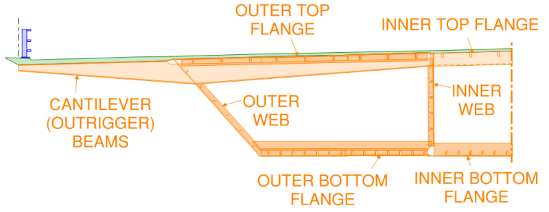
Finally, at the ends of each box segment, a transverse diaphragm plate was provided to tie the flanges and webs together and assist in support of these plates for local bending effects. The image below shows a cut-away view of a typical bridge deck arrangement with varying visibility across its length to show how all the elements came together…
West Gate Bridge Construction Methodology
The royal commission report which investigated the collapse identified the construction methodology as a contributing factor as to why the West Gate Bridge collapsed. For this reason, it is important to understand the construction methodologies and techniques which were proposed for its erection to better understand the failure mechanism.
The specific construction methodology adopted for the West Gate Bridge had not been used previously anywhere in the world at the time.
The construction methodology differed from the lesser spans 10-11, 11-12, 13-14 and 14-15 compared with the main span over the Yarra River (span 12-13). The collapse of the West Gate bridge occurred at a lesser span 10-11, therefore we will take a look at the construction methodology for these lesser spans only.
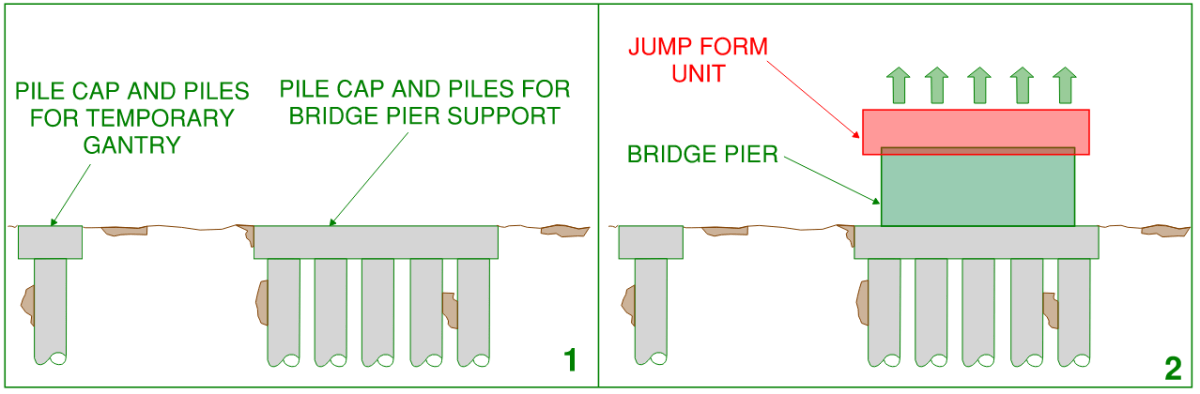
- Firstly the foundation preparation began. This included construction of pies an pile caps to support the bridge piers. Piles and pile caps were also constructed adjacent to the pier locations to support a future temporary gantry which would later assist in lifting the steel box girders. To learn more about pile foundations, different types of pile foundations and their benefits, take a look at THIS article.
- The piers were constructed using a self-jumping formwork system (jump form system). For further explanation on how a jump form system works, take a look at THIS link.
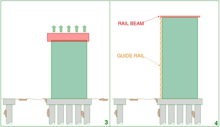
3. The bridge piers continued to rise until the required height was reached.
4. After the bridge piers were topped out, the jump form system was removed and rail beams were installed at the top of the piers. A vertical guide rail was also constructed on the side of the piers.
5. The lifting gantry adjacent to the piers was then constructed as well as temporary support beams which spanned between the lifting gantry and the pier.
6. A temporary working deck was then set-up between the support beams and the steel box girder was constructed at ground level. The steel box girders were constructed in halves, this reduced the lifting weight of the pieces allowing them to be raised easier. The decision to construct the steel box girders in halves would later prove a contributing reason which caused the West Gate Bridge Collapse (which we will cover later on).
7. Once a half segment of the steel box girder was completed, it was then lifted up to the top of the pier.
8. The half segment was then pulled sideways into position using the rail beam which was previously installed to the top of the pier.
9. The second half of the box girder was then completed and lifted to the top of the pier
10. The second half of the box girder was pulled horizontally into position to meet the first half.
11. Once both halves were in position their exact final location was calibrated then the structural connection between the two was completed. (this was a longitudinal bolted seam connection as well as the lateral diaphragms)
12. After the halves were fully connected they were lowered into their final position on the bearing pads and the temporary gantry, vertical guide rail and rail beams were removed.
The First Problem, Construction of Bridge Span 14-15.
The first span of the steel portion of the West Gate bridge to be constructed was span 14-15 (at the eastern end).
Construction of this span, in particular the first box girder half was performed in accordance with the sequencing discussed in the previous section of this article.
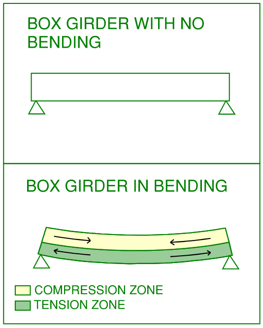
When the half segment was initially lifted from the working deck by the support beams the box girder member was required to be self supporting. The only load it was supporting at this time was its own self-weigh as well as rigging cables and other support systems which were negligible in comparison.
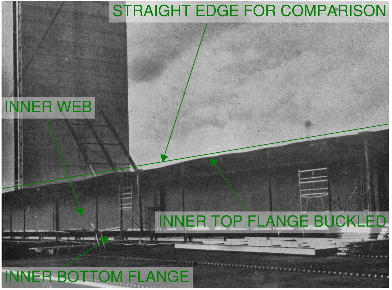
Due to the span being simply supported, the top flange of the half girder underwent compression while the bottom flange underwent tension. In this temporary condition the inner top flange was required to cantilever some 3m (10 feet) from the inner web relatively un-restrained. The lack of restraint coupled with the compression force due to bending caused the outer top flange to buckle.
The extent of buckling was quite considerable with an amplitude up to 380mm (15 inch). The amplitude of the buckling at this magnitude likely caused yielding of the steel to occur. At the time of construction this fact was not identified by the builder or Structural Engineer.
The lack of restraint of the inner top flange was caused by two shortcomings in the temporary support arrangement of the half girder.
Firstly, the temporary bracing support provided to the top and bottom inner flanges was not detailed to restrain against buckling in the upwards direction. It appears that the bracing was principally intended to support the top and bottom flange for local cantilever action under the self-weight of both of these elements only. The bracing elements which were introduced were:
- A vertical compression struct installed at the tips of both the upper and lower inner flanges.
- A tension rod extending from the top of the inner web to the tip of the inner bottom flange cantilever.
The second reason for lack of restraint was the stiffener beams on the top flange did not line up for the full width of the box girder half segments. Instead, the stiffeners which acted as temporary cantilever beams at the un-restrained upper flange were positioned half pitch off-set from the internal stiffener an cantilever beams. This meant that in the temporary case the internal stiffener beams were applying bending moment in the weak direction of the thin walled inner web…
Even with the significant buckling it was decided to continue to lift the half segment to the top of the pier and perform any rectifications at height. This was a very risky and unwise decision considering the extent of buckling may have caused loss of strength in the top flange due to yielding. As previously mentioned, the matter that the steel buckled to the point of yielding was not apparently identified by any of the relevant responsible parties.
The proper decision should have been to lower the half segment to its temporary support at ground level and replace the buckled sections with new steel. Then provide adequate bracing and re-lift the segment into place. The decision to continue with the lift was apparently made in an effort to not delay construction of the next half segment. Although span 14-15 of the West Gate Bridge did not collapse, subsequent reports found that strengthening and steel replacement was required due to the loss of strength from the buckling.
The construction team provided a revised bracing detail to the un-restrained flanges for the next half-segment. This arrangement was a single diagonal angle iron which had both compression and tension capacity which more adequately restrained the top compression flange during lifting…
Although some warping/buckling still occurred, this arrangement resulted in a much straighter free edge for the top and bottom flanges.
When both halves of the steel box girder were pulled into position and were sufficiently close, it was found that the flange plates were out of tolerance. The construction technique of lifting the box girders in halves and joining them only when in their final position required that the construction tolerances for both needed to be very small.
The out of tolerance positioning of both halves were caused not only by the warping of the steel flange plates due to buckling but the pre-cambering between the two halves was off by approximately 90mm (3.5 inch). Since the flanges were buckled well beyond this figure, the datum points were taken from the inner web of each half segment. The diagram below shows a stick figure exaggeration of this arrangement…
To rectify the out-of-tolerance arrangement of box the girder halves the following measures were then implemented on-site…
- The buckled flange was straightened by applying a universal beam along the edge of the flange. Bolts were then drilled tight through pre-drilled holes in the universal beam and the already present bolt holes on the flange plate which were to later accept the connecting bolts for the longitudinal seam connection between the two box girder halves. These bolts were later discarded and their only purpose was to assist with the straightening of the flange plates.
- The out-of-position location was rectified by jacking up the left-hand-side half so that the two halves were at the correct location at mid-span. After the mid-points were located the middle lateral diaphragm was installed. After this installation the construction crew were able to “zipper up” the remaining lengths either side working their way from the middle outwards. Subsequent transverse diaphragms and the bolted seem joint were progressively pulled together using localised hydraulic jacks at each diaphragm location.
It would be later found in the royal commission report for the collapse of the West Gate Bridge that this process of jacking and wrestling the two segments into position likely introduced locked in stresses and further yielding to some of the steel sections of span 14-15.
Collapse of Span 10-11
After the “successful” completion of span 14-15 the construction team moved to the mirrored identical opposite span at 10-11.
The construction sequence was largely the same with the only modification being that both halves of the box girder were provided with the diagonal angle iron strut to ensure that the flanges were prevented from buckling as they were lifted.
However when both box girder halves were placed into position, an out of tolerance magnitude of 100mm existed (4 inch). This tolerance is well outside of regular construction tolerance limits, even for a relatively complex procedure which was proposed for West Gate Bridge. A tolerance of at most 25mm (1 inch) but more likely around 15mm (0.6 inch) should have been achievable. At this lower tolerance, it would have been much easier to pull the two halves into their final positions with only minimal assistance from rigging equipment.
It was later found through investigation of the construction techniques at ground level, what caused the excessive error in the cambers for both box girder halves of span 10-11…
When the box girder halves were constructed at ground level they were constructed on top of a temporary support trestle. The support trestle allowed the box segments to be placed end to end at the required pre-camber height. It is common practice to pre-camber bridge spans to control overall long term deflection. Pre-cambering is the process of introducing upwards deflection to a structural member (through bending or hot rolling or fabricating the member in a gentle arch shape). This is in anticipation that once the member is loaded and is fully spanning, the resultant deflection under its loading and bending will result in a somewhat “flat” member.
There were concerns within the construction team of the West Gate Bridge however that temperature differential between the top and bottom flanges caused by sunlight would artificially increase the pre-camber. The principle being that the top flange would be exposed to direct sunlight and would heat faster and therefore expand in comparison to the relatively cool bottom flange thus resulting in a further upwards curvature.
It was though that this would cause the bridge span to lift off of the support trestle at mid-span and place additional loading on the ends of the trestle and its temporary foundations. The below elevations visually represent this phenomenon. Note that the pre-camber and additional curvature due to differential temperature are grossly exaggerated in the images to add clarity to the both conditions…
Instead of providing additional strengthening to cater for this effect, the construction team decided upon an elaborate jacking arrangement to ensure that all portions of the box girder remained in contact with the support trestle thereby evenly distributing the load along its length.
This involved placing hydraulic jacks between the underside of the box girder and the top deck of the support trestle.
The jacks were interconnected on a common pressure line to control their load. The theory was that the pressure within the line was to be set to a level somewhat less than that required to sustain the full weight of the boxes. This would ensure that the jacks were fully “grounded” (bottomed out) when there was no temperature difference to induce the additional curvature.
Setting of the trestle heights for the intended pre-camber was to be performed at dawn to ensure no differential temperature effects existed and therefore having the jacks bottomed out thus providing a solid and measurable datum point of reference. Re-surveying and re-calibration of the camber height was required as the box girder was progressively being constructed. This re-calibration process would have been normal practice for construction of this type.
Although the jacking arrangement would have worked in theory, in practice it proved to cause difficulties in construction. Only a few degrees temperate differential would have set the “floating system” into effect. It would be later found that through investigations into the West Gate Bridge collapse that:
- Many on the construction team did not fully understand how the jacking system worked
- Survey data was not always taken at dawn which therefore provided false measurements
- The jacking arrangement spent more time in the “floating” state than the “bottomed out” state which prevented an accurate datum point being established. It was likely that the majority of the span was constructed with an inaccurate datum assumption.
Considering the larger out-of-tolerance situation and the matter that the construction team were seeking a faster rectification method compared with span 14-15, a different approach was adopted for bringing the two box girder sections together. The proposal was to place large concrete blocks on the half span which was higher in camber. This would cause the half segment to deflect downwards to become closer to the required tolerance.
Seven concrete blocks were placed on one segment half which totalled around 25 tonne (56,000 lbs). Soon after the blocks were placed, a significant buckle was observed in the top flange of the loaded box girder.
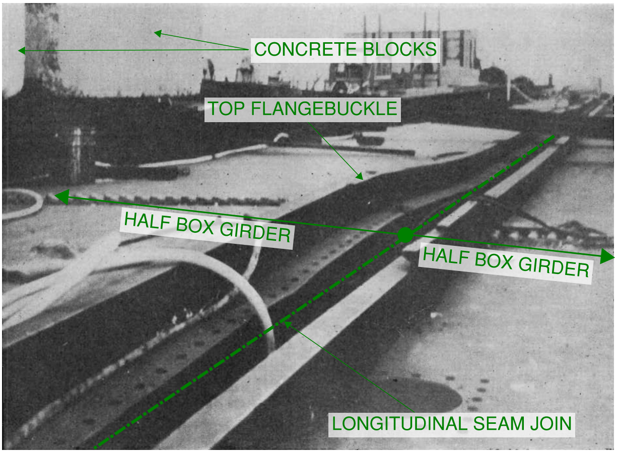
Further loading of the higher half segment was abandoned. Further subsequent investigation into the West Gate Bridge collapse indicates that the engineer who approved the loading did not have adequate information to make the determination accurately. The bending capacity of the half segment was determined for a horizontal neutral axis assumption. However due to the asymmetry of the half box section, a slanted neutral axis would have resulted. This would have meant that in reality, the effective depth of the half box girder and therefore its bending capacity diminished with increased distance away from the internal web.
It would appear that due to the introduction of circa 25 tonne of loading and the error in the neutral axis assumption caused the half box girder to be over-stressed and would prove to be one of the dominos which caused the collapse of the West Gate bridge.
After the buckle in the top flange was identified, there was circa 25mm (1 inch) of camber difference which remained between the two halves. This remaining difference was taken out through introduction of jacks, similar to the process undertaken on span 14-15.
The construction crew managed to connect the majority of the transverse diaphragms joining the two box girder halves with the exception of one. The remaining transverse diaphragm was the one closest to the buckled flange location. It was found that the top flange plate was so distorted that the attached fin plates were buckled out of position and could not be bolted. It was obvious that the buckle needed to be “ironed out” in order to allow the final transverse diaphragm to be installed.
Because the majority of the two halves were structurally tied together, the decision was made to remove the concrete blocks which were loading one half segment of the box girder.
The buckle needed to be flattened in order to effectively remove it. However with the two halves mostly tied together there was nowhere else for the crimpled material to go. The only effective way for the buckle to be ironed out was to locally remove the top bolts within the transverse seam joint at the flange (where the box sections were joined end to end).
Remember that the box girder is currently spanning unsupported between its support piers at this time. The bending induced due to its self weight is now placing compression force on the top flange and tension force on the bottom flange.
The methodology to flatten the buckle proposed was to be similar to that adopted for the buckling of the previously effected 14-15 span. The bolts within the transverse seam joint were to be locally removed adjacent to the buckle then a universal beam provided as a “strong back” for the material to be pulled back against into straight position. Here is a cross section simplified sketch of the intended methodology to remove the buckle in the top flange…
The intention for the bolt removal was to begin at the middle of where the two half segments met and work in an outwards direction towards the outer edge of the half segment. Due to the compression force within the top flange, as bolts were loosened the flange plates slid across each other. This caused the bolts to become jammed, preventing them from being removed. This is a clear indication that in the process of removing the bolts, the construction team were taking away a primary load path within the box girder. With the removal of each bolt, the load was being re-distributed to other regions within the box girder and being concentrated over a smaller area.
To overcome the issue of the bolts becoming jammed within their bolt holes, it was decided to use the airguns to overtighten the bolts to failure. The force produced by the sudden fracture of the bolts was enough to not only “undo” the bolts but also force them out of their bolt holes.
Eventually after a number of bolts were removed (some 30 or so bolts) the buckle was seen to become worse and the workers on the box girder noticed a gentle settlement as the half box girder deflected further.
The half box girder which was effected by the buckle had now structurally failed. The only apparent element preventing the segment from collapsing is the load share and support assistance provided by the relatively in-tact and non-buckled opposing half segment. The worsening of the buckle was immediately apparent to the site crew. They were oblivious to the fact that roughly 50 minutes after the buckle got worse, the West Gate Bridge would collapse catastrophically.
The collapse of the West Gate Bridge was cause by a combination of the original buckle which was caused by overstressing due to the applied dead load from the concrete blocks. This was made worse through removal of the bolts which caused concentrated stresses to then exist in the remaining portions of the half segment that were still in tact.
Collapse Sequence of the West Gate Bridge
From eye witness accounts as well as inspection of the collapse debris for the West Gate Bridge, investigators were able to determine the collapse sequence for span 11-12.
- The buckled location close to mid-span for the box girder provides the hinge point for collapse to begin. After this point had structurally failed, the bridge had now become a mechanism with support conditions being roller, pin, pin (from let support, mid span to right support).
- The end immediately above pier 11 was provided with an expansion joint (roller support). The falling box girder pulled its tip off of pier 11 and this half of the span continued to fall in an almost horizontal orientation.
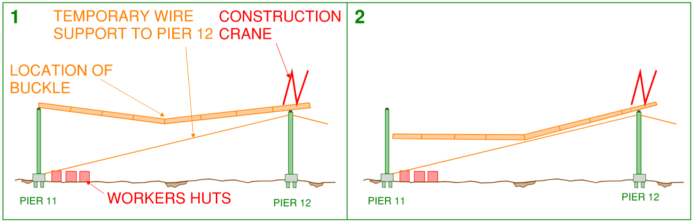
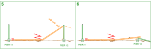
3. As the girder continued to fall it struck the temporary tension rod support which was stabilising pier 12. The small cantilever portion over pier 12 rotated anti-clockwise causing the temporary construction crane which was sitting on the bridge to be flung towards mid-span almost like a catapult.
4. The half span closest to pier 11 landed on several site worker huts. Upon impact, angular (rotational) momentum generated on the opposing half span closest to pier 12 caused it to rotate to an almost vertical position.
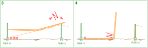
5. The half span closest to pier 12 then changed direction due to the gravity forces acting upon it and its tip struck the side of pier 12.
6. The force of impact from the box girder span on pier 12 then caused it to collapse.
One thought on “WHY DID THE WEST GATE BRIDGE COLLAPSE”