
Structural Engineers design buildings to withstand the forces of mother nature. Often these forces are hard to predict, so engineers develop mathematical models to quantify their behaviour. The response of buildings to these elements is also somewhat hard to predict. It has often been through catastrophic events that Structural Engineers better understand why buildings collapse due to earthquakes…
“Engineering is the art of modelling materials we do not wholly understand, into shapes we cannot precisely analyse, so as to withstand forces we cannot properly assess, in such a way that the public has no reason to suspect the extent of our ignorance“
That is a quote from Dr. A. R. Dykes, British Institution of Structural Engineers and a very succinct summary of how structural engineering can be just as much an educated guess as it is an exact science. This quote is perhaps most true when discussing the effects earthquakes have on buildings.
There has been some substantial improvements in the understanding of seismic behaviour in the last number of decades. Some key reasons why buildings collapse due to earthquakes include:
- Plan and stiffness irregularity
- In-sufficient ductility
- Column failure due to “short column” effect
- Poor connection detailing between primary structural support members
- Soil failure caused by liquefaction
- Rigid Structure
- Inadequate lateral Strength
- Lack of understanding of design codes by Structural Engineers
This article will explore the reasons buildings collapse due to earthquakes from a Structural Engineering and practical perspective. To help explain some of these reasons we will be looking at the collapse of the CTV building in Christchurch New Zealand as a case study. For a beginner look at earthquakes and its effects on buildings take a look at THIS previous article for further reading.

Plan and Stiffness Irregularity can cause Buildings to Collapse due to Earthquakes
Plan and stiffness regularity is a vital component in seismic design. It also has the most fundamental affects on the buildings layout and aesthetics. Therefore it is crucial that the coordination between architecture and structure is thoroughly resolved. But what is plan and stiffness irregularity?…
Plan stiffness irregularity in buildings is where a buildings lateral stability elements are located eccentric from the buildings centre of mass. Stiffness irregularity can also occur between floors where lateral stability elements abruptly terminate or begin.
Looks look a little closer at plan stiffness irregularity… A buildings behaviour due to earthquake shaking is dependant upon:
- The buildings centre of mass
- The the buildings centre of stiffness
- The distance between a buildings centre of mass and centre of stiffness.
Centre of Mass
The centre of mass of a given floor plate is dependant on its geometry and thickness. The best way to imagine the centre of mass is to identify a point on the slab geometry where if you were to provide a single point of support the slab would remain stable (like a see-saw).
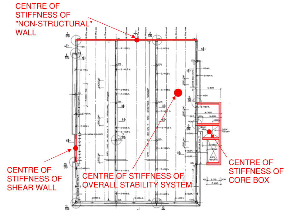
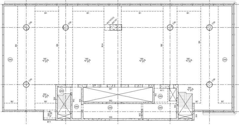
Lets look at the CTV buildings typical floor plan as an example. The construction of the CTV Building generally comprised the following elements:
- Concrete Columns
- Precast concrete beams
- Composite concrete floor which used a profiled metal sheet for both formwork and reinforcement
- Shear walls in the form of a concrete core and one discrete shear wall.
- An architectural pre-cast concrete fascia around more than half the perimeter of the building.
Here is a plan view of the floor plate indicating each structural element…
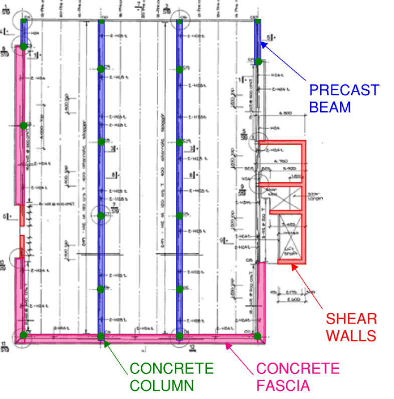
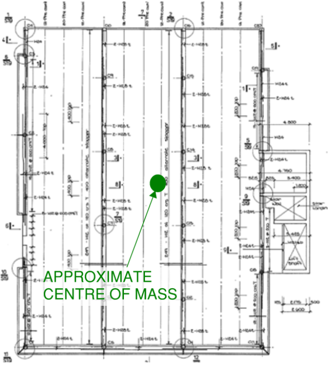
Lets now identify an approximate location of the centre of mass. The floor is a simple rectangle which is quite easy to determine its geometric centre. The buildings core (to the right of the plan which houses the lifts and stairs) will skew the centre of mass slightly to the right due to the cluster of walls. Note that all elements contribute to the buildings centre of mass including the shear walls and columns, not just the floor itself…
Centre of Stiffness
The centre of stiffness is a little harder to determine. It can be identified mathematically by calculating the stiffness of each lateral stability element. The weighted average for the centre of stiffness of each individual element supporting a floor plate laterally is the location of the buildings overall centre of stiffness. The stiffer an element is, the more “weight” it holds in the weighted average calculation.
The stiffness of an element is highly dependant on its structural depth and its construction material. The second moment of inertia equation which influences an elements stiffness is as follows (for a rectangular element)…
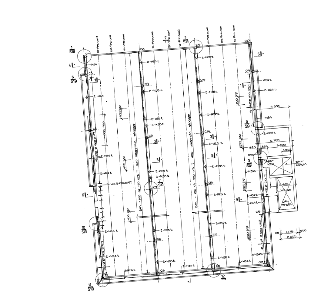
The CTV Building comprised two lateral stability elements, the core box to the right of the floor plate and a discrete shear wall to the left. (For an in-depth look at what stability systems are and different types of stability systems for structures, refer to THIS article). The stiffness of the core box is far higher than that of the discrete shear wall, therefore the centre of stiffness of the overall system is skewed to the right of the floor plate towards the core box…
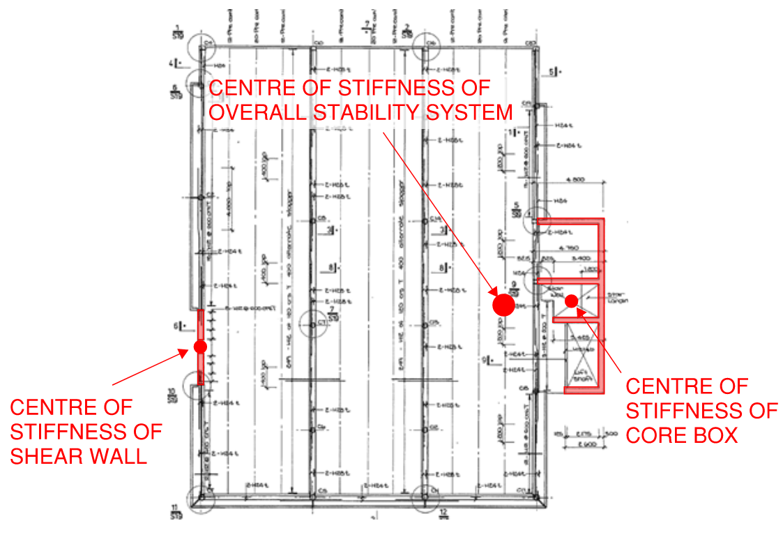
There was an unfortunate oversite in the detailing of a northern structural wall on the CTV Building. The northern wall was a blockwork wall which was intended to be non-structural.
While sketches within the computations indicated it to be structurally separated from the slab, the final drawings failed to indicate this requirement. This resulted in the northern wall contributing to the overall stability systems stiffness….
Considering its long length, this non-structural wall further skewed the centre of stiffness towards the top of the floor plate. Taking this into consideration we can now modify the buildings centre of stiffness to obtain its final true location…
Distance between Centre of Mass and Centre of Stiffness
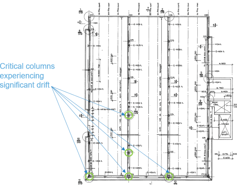
Plan stiffness irregularity is generated when the centre of mass is located a distance away from the the centre of stiffness. Using the CTV building example again, we can show both of these points on the same image…
The eccentricity between the centre of mass and centre of stiffness tends to produce a torsional response on the building (twisting action) when the building is set into motion due to earthquake shaking. The larger the distance between the centre of mass and centre of stiffness, the more severe the torsional response will be.
Notice in the animation above, due to the torsional response of the building, the columns located to the bottom left corner of the floor plate are exposed to magnified lateral displacement. This increased lateral displacement magnifies the inter-storey drift (difference in lateral movement from one storey to another) which places higher stress demand on the column-beam joints. This increased stress demand on columns due to plan irregularity of stiffness has been identified as a reason why buildings collapse due to earthquakes…
In-sufficient Ductility can Cause Buildings to Collapse due to Earthquakes
Some building materials perform better than others in an earthquake. The more ductile your construction material the better.
Ductility is the structures ability to dissipate energy from earthquake shaking through yielding and/or deformation. Brittle materials are those that will fracture and break under small deformations while ductile materials bend and remain in-tact at high deformations.
Seismic design codes rate different construction types using a ductility factor. The higher the ductility factor, the higher the ductility of the structure. The table below illustrates some example ductility factors as specified in the Australian Seismic Design Code AS 1170.4…
| Construction Type | Ductility Factor |
| Steel Moment-Resisting frame | 4 |
| Steel Limited Ductile Concentrically braced frames | 2 |
| Concrete Intermediate moment-resisting frames | 3 |
| Concrete Ductile Shear Walls | 3 |
| Concrete Limited Ductile Shear Walls | 2 |
| Timber Shear Walls | 3 |
| Timber Moment Resisting Frames | 2 |
| Unreinforced masonry | 1.25 |
Column Failure due to “Short Column” Effect
Short column effect is possibly the most overlooked phenomenon in seismic design. This is largely due to the fact that short column effects are usually generated by non-structural elements. But what is it?…
Short column effect in seismic design is where some columns on a given floor plan have their effective length restricted or reduced. This may be caused by several factors including a mezzanine floor, low level crash walls in car-parks or internal partial height blockwork partition walls. This results in the the shear force within these columns being magnified significantly compared to the other columns on the floor plan with full effective height.
If this effect is not adequately considered by Structural Engineers it can be a primary reason why buildings collapse due to earthquakes. Columns which are susceptible to this phenomenon need to be specified with additional shear reinforcement to ensure strength and adequate ductility. The video below shows footage from a scaled test where a model structure underwent test shaking and the short column effects can be plainly seen…
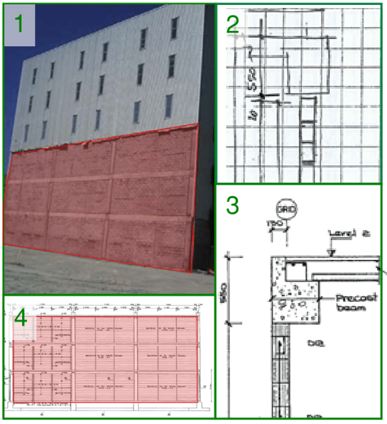
The CTV building in Christchurch had perimeter columns which were susceptible to this short column effect. As part of the visual appearance of the building, the architect specified pre-cast concert fascia elements. This gave the building a horizontal banded appearance with glazing and concrete alternating in a horizontal striped pattern.
Inadequate separation between these pre-cast concrete fascia elements and the vertical support columns would have made these perimeter columns susceptible to increased shear load due to short column effect. Below is a plan view of this arrangement. It is not clear in the structural documentation how much clearance should have been provided between the edge of column and the end of each fascia panel.
Poor Connection Detailing Can Cause Buildings to Collapse due to Earthquakes
Even if the primary structural elements are well proportioned and designed to withstand the seismic design forces, poor detailing can still cause a building to collapse due to earthquakes.
In-fact, a building which contains under-strength elements will still survive a substantial earthquake event if the connection details are robust and well considered. Connections which are most critical for determining a buildings performance in a seismic event are:
- Beam to column connections
- Beam to slab connections
- Vertical load-bearing system to lateral stability system (slab/beam to shear wall for example).
Lets look at a handful of details in the CTV building to identify some of the connection detailing which may not have been robust enough under seismic conditions.
Beam to Column Connections
The beam construction for the CTV building utilised pre-cast concrete construction. The construction sequence was as follows:
- Support columns were constructed
- Pre-cast beams lowered into place
- Metal tray profiled formwork placed between beams
- In-situ topping slab poured over metal tray formwork as well as pre-cast beams
- Sequence repeated for subsequent levels
Below is a snapshot from the structural documentation of the CTV building for a typical pre-cast concrete beam…
Here is a sketch view of the entire beam and column assembly in the final case…
This connection detail is adequate for the vertical load condition where the floor and beam supports the self weight and applied load. The bending moment configuration changes however during an earthquake. First lets take a look at the simple bending moment diagram for the vertical load condition…
Because the beam is continuous over the column we are left with the simple bending moment diagram illustrated above… negative bending over the column resulting in tension in the top layer of reinforcement and compression in the bottom half of the beam.
In an earthquake event however, as the building sways from side to side at large displacements, this then triggers an interaction between the column and the beam. The behaviour is similar to a moment-resisting frame or a portal frame (for an in-depth article on different types of stability systems in buildings refer to THIS article).
This interaction occurs even if the Structural Engineer has assumed that the primary stability support is provided by the core and shear walls…
As we can see, there is a possibility that a reversal bending may exist at the beam-column joint. This can result in tension in the beams bottom layer of reinforcement in the beam at the column location.
The detailing within the CTV building was such that the bottom layer of reinforcement was not sufficiently developed for tension in the bottom layer of beam reinforcement. For a full article on an in-depth discussion about reinforcement, development length and pull-out failure, take a look at THIS article.
A plan view perspective of the beam-column connection reveals the in-sufficient embedment provided to the bottom reinforcement…
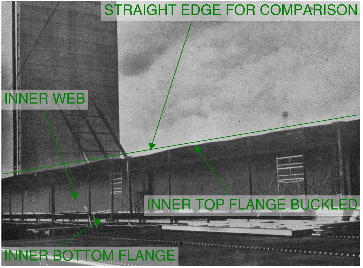
The beam-column joint in the CTV building was identified in the subsequent enquiry as a possible reason why the building collapsed due to the earthquake. Below are a selection of three images showing the beam ends as they were viewed after the collapse…
Another critical joint in buildings which require special attention by Structural Engineers are construction joints. For further discussion on different types of construction joints in slabs and how to analyse them, take a look at THIS article.
Beam so Slab Connection
Similarly with the beam-column connection, the detailing for the slab-beam connection did not adequately account for the reversal moment caused by earthquake shaking.
Lets take a look at a detail section which indicates what was built…
The construction sequence for the slabs were as follows:
- Column was constructed
- Pre-cast concrete beams were lowered and placed on columns
- Metal tray formwork was placed between the beams (the so called “hi-bond” formwork acted both as temporary formwork as well as bottom reinforcement for the slab in teh final case)
- The slab was then poured in-situ, with concrete being poured over the pre-cast beams as well as the hi-bond formwork.
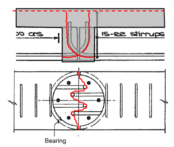
Lateral movement of the building due to earthquake shaking would have tended the pre-cast beam to rock/rotate back and forth causing torsion to generate within the beam. The torsion in the beam would have been restrained by the adjacent slabs. This torsional effect had the potential to impart a negative moment and therefore tension in the bottom reinforcement layer of the slab (similar to the beam explored earlier for the beam-column connection). Here is an animation of what this may have looked like…
Torsion or rocking of the beam would have generated a crack pattern around the pre-cast beams starter bar reinforcement as indicated below…
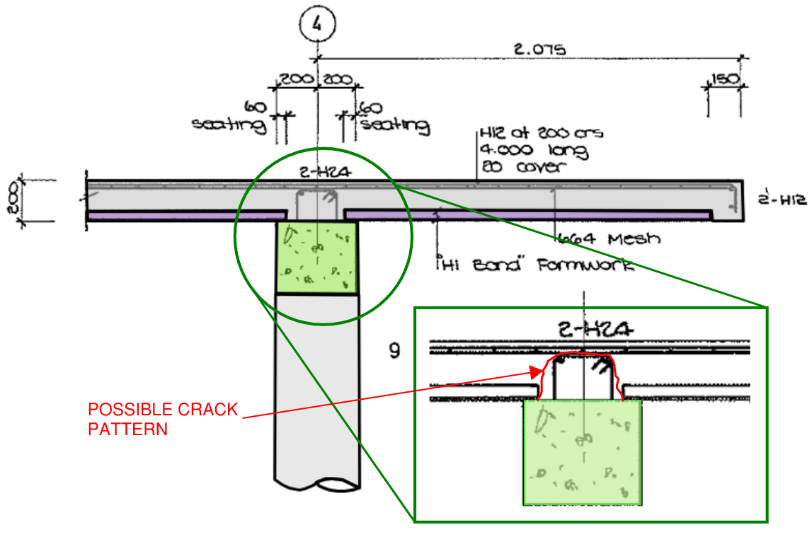
Adequate bottom reinforcing bars at the beam-slab joint would have prevented this crack from propagating and spreading around the beam head…
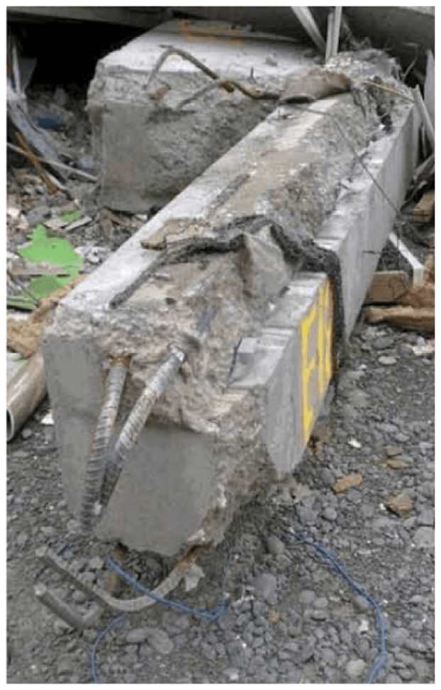
The image below shows an image of a beam top from the CTV building after its collapse. Notice the clean face of concrete where it is evident that the beam delaminated away from the slab in keeping with the crack pattern illustrated earlier…
Slab to Shear Wall Connection
The most critical connections in a building with respect to earthquake design is that of the connection between slab/beam and the shear walls. Shear walls within a building are generally the primary lateral support element which resist earthquake loading. Delamination of a shear wall to its adjacent floor slab can lead to catastrophic collapse of a building due to earthquakes.
This was found to be a main reason why the CTV building collapsed in Christchurch during the 2008 earthquake experienced there.
Lets take another look at the typical floor plate of the CTV building. Keep in mind that we have already identified that the floor plate had a tendency to not just translate side-to-side but also rotate due to the eccentricity between the centre of mass and centre of stiffness. This would have lead to a push/pull coupling between the core walls and the slab as indicated below…
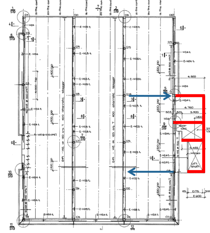
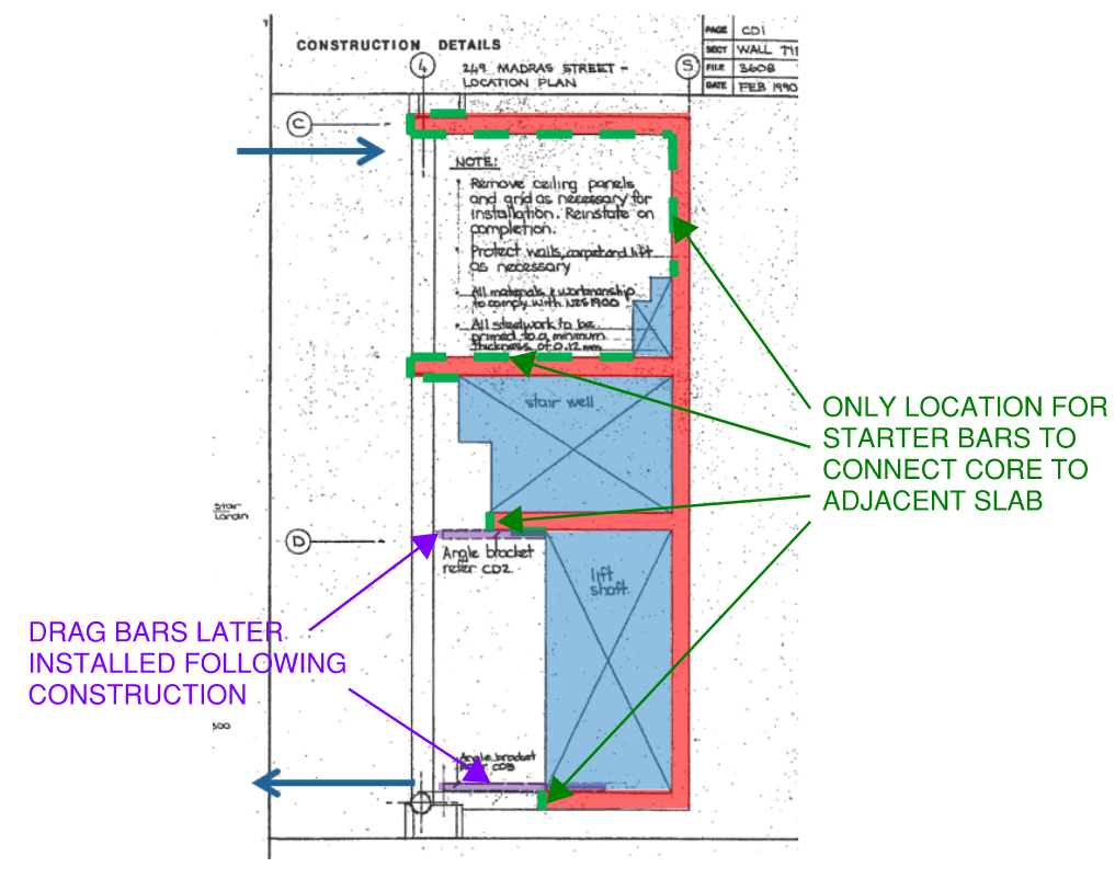
The only element connecting the floor slab to the core box immediately after the building was constructed was the reinforcing starter bars protruding from the core walls themselves.
A detailed look at the core shows just how little opportunity there was for starter bar reinforcement to connect the shear walls to the slab. This was due to the the location of the services and lift openings and the layout of the walls.
The connection was so minimal that prior to the first tenant moving into the building additional strengthening was provided at this connection point. This was prompted through a third party Structural Engineering review which was performed as part of the new tenants due diligence prior to moving into the building. The strengthening was achieved through introduction of two post fixed “drag bars” which were steel equal angle members bolted to the slab soffit and inside face of the core walls…
Soil Failure due to Liquefaction can Cause Buildings to Collapse due to Earthquakes
Soil can drastically lose its strength when liquefaction occurs. Liquefaction is when an otherwise solid soil structure behaves temporarily as a liquid (usually produced by ground shaking).
Soils prone to liquefaction are those which are loosely packed (un-consolidated) and contain a high moisture content. When the ground shakes, the loosely packed soil begins to consolidate (the soil particles begin to settle and fill the air voids within the soil mass). As consolidation occurs, any water which is present within the voids deep in the soil becomes pressurised. As the water is pressurised there is no where to go but upwards through the soil mass. The upwards pressure of the water causes the soil structure on the upper layers to become buoyant, resembling the behaviours of a viscus material (liquid).
The effects of liquefaction can be devastating to structures. Structures most effected by liquefaction are those founded on shallow foundations. Liquefaction can ultimately cause excessive differential settlement which may overstress the shallow foundations causing structural damage.
Behaviour of Rigid Structures During Earthquakes
How flexible or rigid a structures is has a large influence on the resultant loading on the building during an earthquake. This can also be a reason why a building may collapse due to earthquakes (if not adequately considered by the Structural Engineer!).
A buildings flexibility can be loosely measured from its fundamental period. For a thorough look at period, frequency and modes of vibration/oscillation, take a look at THIS article.
A period of a building is how long it takes to complete a single side-to-side oscillation of movement after it is set into motion. A building with a longer period (in seconds) can be said to be more flexible than a building with a shorter period (which would be more rigid).
Lets take a look at a mathematical representation of this with respect to earthquakes. When determining the seismic force on a building, the spectral shape factor needs to be determined. The spectral shape factor heavily influences the resultant magnitude of the seismic load applied to the building. The graph below shows its relationship with the buildings period (shown on the horizontal x axis)…
From the graph above, we can see a significant increase in spectral shape factor (and therefore earthquake force) when a buildings period reduces from around 1.5 seconds to 0.5 seconds (i.e. becoming more rigid). This is a main reason why buildings become less and less earthquake governed and become more and more wind governed as they increase in height (taller buildings generally having a larger fundamental period).
This is also why shorter and more stiff buildings have a higher risk of collapse due to earthquakes if they are not designed and detailed correctly. In seismically sensitive regions Structural Engineers may look to make their buildings more flexible. This is counter-intuitive especially when compared to a wind design approach where the stiffer the building, the better (9 times out of 10).
Inadequate Lateral Strength can Cause a Building to Collapse due to Earthquakes
If the building was designed and constructed prior to seismic design needing to be considered in local design codes, this may be a reason for a buildings collapse due to earthquakes.
In Australia for example the first revision of the Australian Seismic Design Code was released in 1979. Since 1979, research and understanding of the effects of earthquakes on buildings have improved which has resulted in revisions being made to the original 1979 code.
Generally the design requirements have become more stringent and more refined as time has gone by. The most significant update to the seismic design code occurred in the early 1990's, after that a further significant update was made in the early 2000's.
Therefore buildings in Australia constructed prior to 1979 are unlikely to have been designed to consider seismic loading at all.
However even in regions where seismic design is required and mandated by local design codes, Structural Engineers can sometimes get it wrong…
Lack of Understanding of Seismic Design Codes by Structural Engineers
There is often a lack of understanding from Structural Engineers about how buildings behave in earthquakes and how to adequately design and detail them to be robust enough to withstand earthquake events.
One of the main reasons for this website, Sheer Force Engineering, is to provide a location for reference material to assist experienced and in-experienced structural engineers expand their knowledge in the art of Structural Engineering.
If you would like to contribute to the growth of this website or learn more about Structural Engineering, sign up to follow the release of future articles and updates via the “Follow Blog Via Email” section right at the bottom of this page.
One thought on “WHY DO BUILDINGS COLLAPSE DUE TO EARTHQUAKES”