
Why Do Retaining Walls Fail
Retaining walls are among the most failure-prone structures due to the many forces acting on them. This article explores the most common reasons retaining walls fail, including rotation, sliding, global stability failure, and local member failure. Using L-wall and soldier pile wall examples, it explains how poor drainage, excessive surcharge loads, inadequate soil investigation, insufficient footing or pile embedment, and detailing errors can undermine performance, and outlines the engineering principles used to prevent these failures.
Quentin Suckling · October 2021 · 11 min read
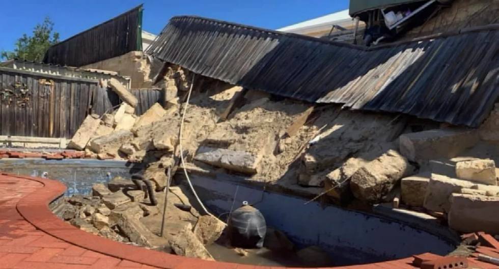
If there is ever a structure which is the most susceptible to failure it would be the humble retaining wall. This is because there are a number of things that can go wrong with retaining walls. And if you believe in Murphy’s law… whatever can go wrong, will go wrong. So why do retaining walls fail anyway? Let's take a closer look…
As always, let's first define what we are looking at before jumping in…
Retaining walls are rigid wall structures intended' to laterally support soil. Soil is usually required to be retained when an abrupt change in ground level is required for a given development site. Retaining walls are generally designed to support the horizontal soil load as well as additional surcharge load which may be applied to the soils surface. In the case where retaining walls lie beneath the water table, they may also support hydrostatic pressure from ground water unless drainage is provided.
Now, let's take a look at several types of retaining walls and apply Murphy’s law…
Failure of Conventional “L-Wall” Retaining Walls
One of the most common retaining wall types is the “L” wall. The L-wall type retaining wall can have a number of different variations. Let's take a look at some of its features…
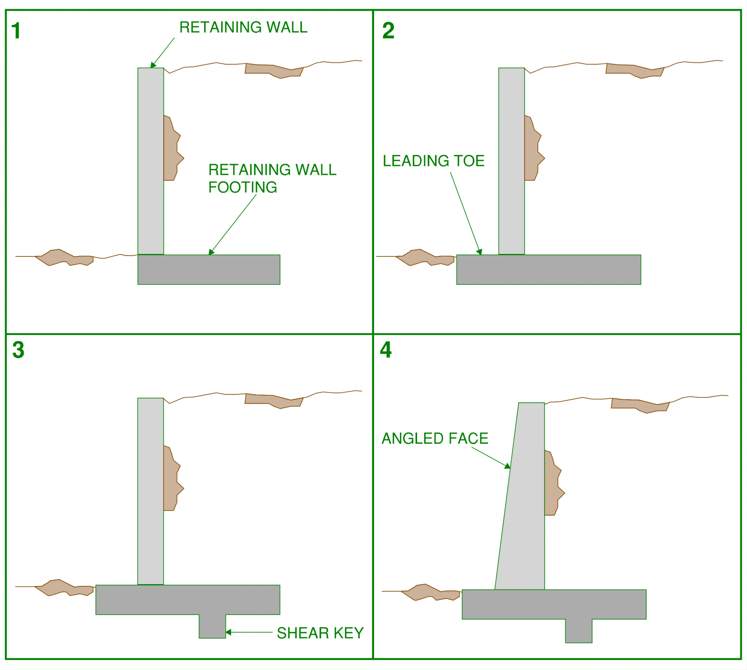
Lets take retaining wall number 2 as our example to see why this retaining wall fails.
Rotation Failure of L-Wall Retaining Wall
A common way that L-Wall retaining walls fail is through rotation. Here is what it may look like…
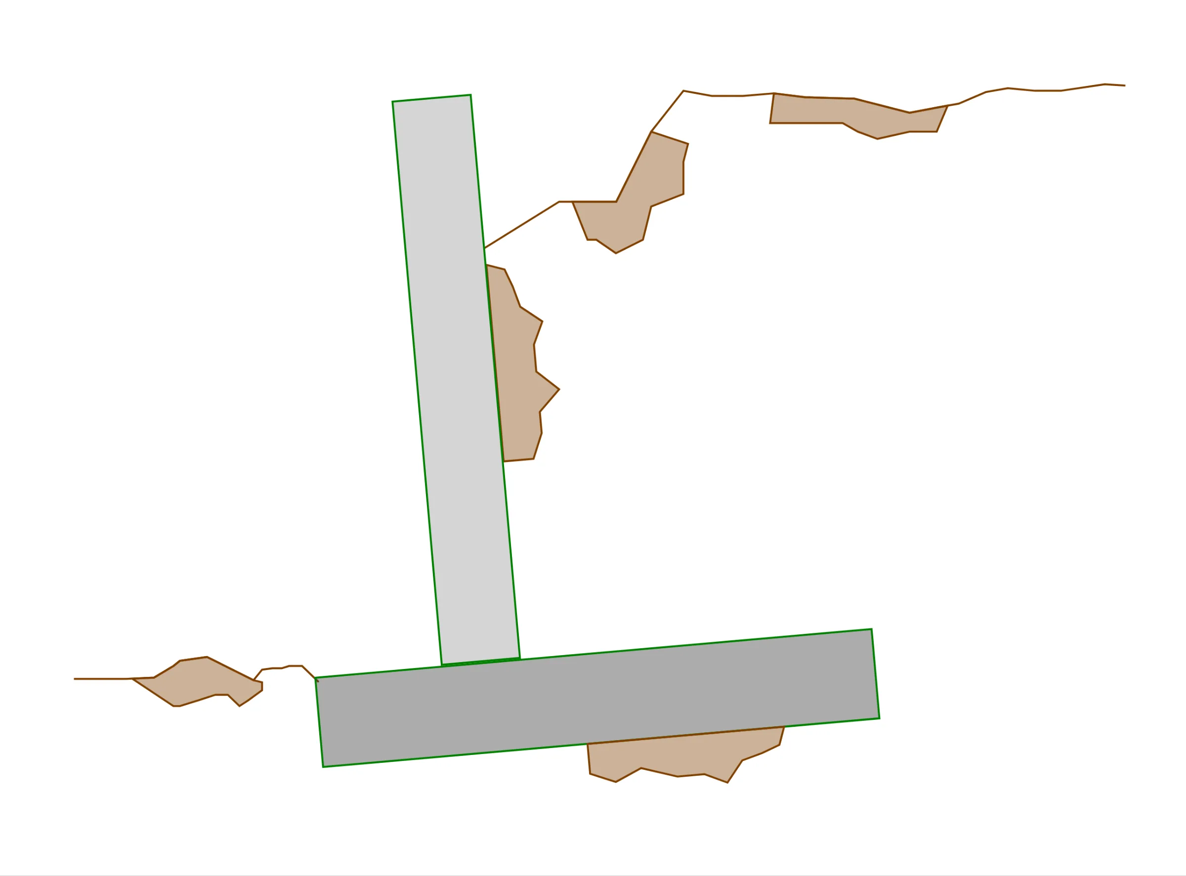
To understand what may cause this rotation failure, let's take a look at the L-Wall again pre-failure. This time we will look at what is ceasing the wall to topple over and what is tending to stabilise the wall…
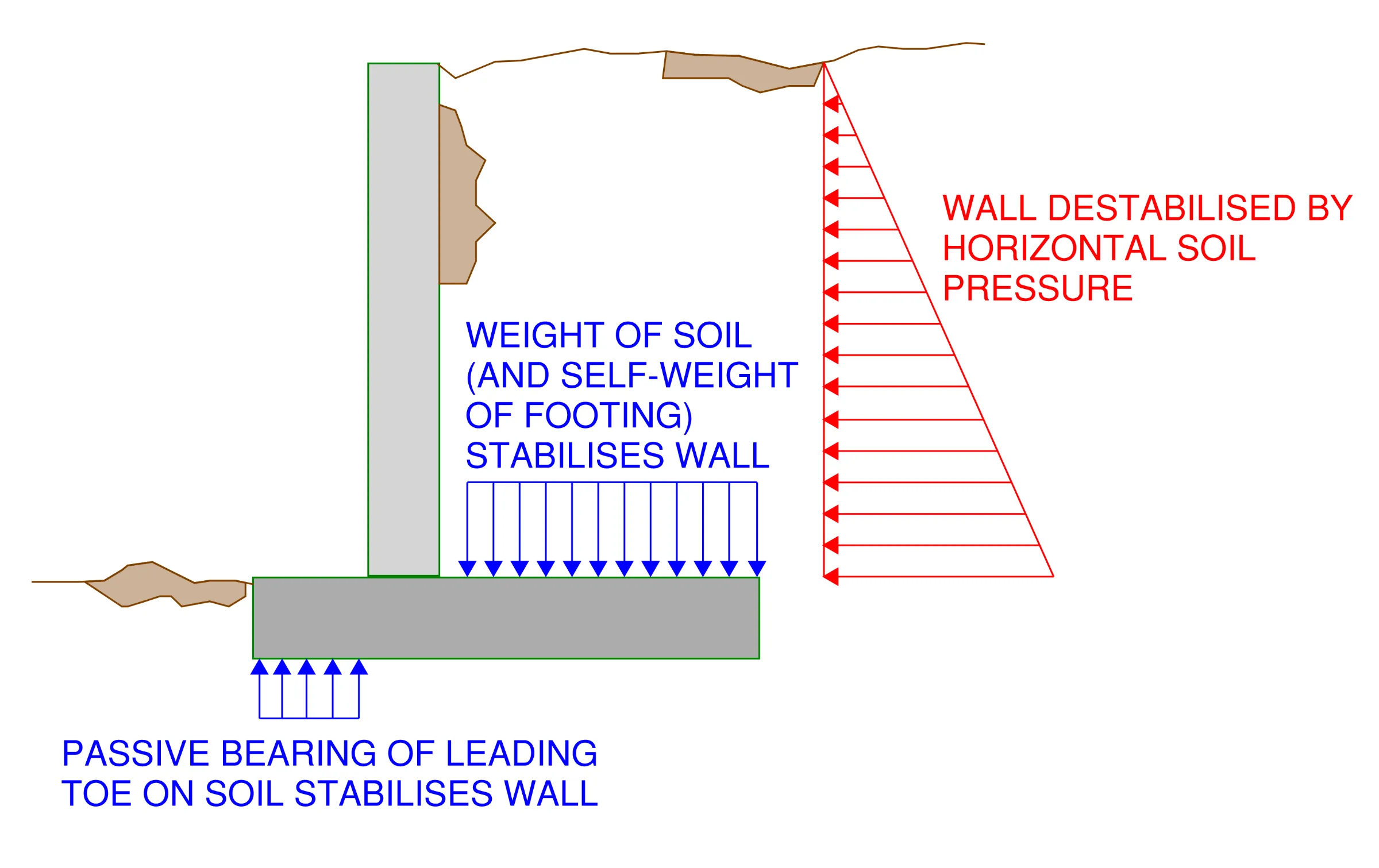
The diagram above is simplified for clarity, but essentially there are stabilising and destabilising forces at work on the L-Wall.
The horizontal component of the soil pressure tends to push the wall over (destabilises the wall)
The vertical component of the soil directly above the back of the retaining wall footing tends to prevent the wall from toppling over (it stabilises the wall). The self-weight of the footing also contributes to the stabilising effects.
Passive bearing of the soil on the leading toe of the footing also tends to prevent the wall from toppling over (it stabilises the wall).
Using the principle of equilibrium we can now determine what needs to go wrong to cause this retaining wall to fail in rotation. (for more on the principle of equilibrium and statics, take a look at THIS article where I go through the first principles approach to truss design and cover the principle of equilibrium in respect to truss nodes).
Too Much Destabilising Force
Increasing the destabilising force on the retaining wall can cause rotation failure. This may occur for a number of reasons:
The density (weight) of the backfill placed at the rear of the wall is higher than the design assumption.
The sub-soil drainage may have become blocked which causes the soil to become saturated. This may mean that the wall is not only required to support the horizontal load from the soil but also the hydrostatic pressure from the moisture (groundwater) as well. The forces exerted as a result of hydrostatic pressure can be significantly large, to learn more about hydrostatic pressure and how it relates to buildings, take a look at THIS article.
Heavy loading may be placed on the surface of the soil on the high-side of the wall. This is referred to as a surcharge. A large surcharge may result in higher horizontal load placed on the back of the wall.
Insufficient Stabilising Forces
Conversely, insufficient stabilising forces acting on the wall can also cause the retaining wall to experience rotation failure. This may also occur for a number of reasons:
Length of the footing is insufficient caused by design error.
Bearing capacity of the soil directly beneath the leading toe of the footing may be insufficient to support the applied force as the wall begins to rotate.
Thickness (and therefore self-weight) of the footing is insufficient.
Sliding Failure of L-Wall Retaining Wall
Another way that L-Wall retaining walls fail is through sliding failure. Let's see what this failure mechanism looks like…
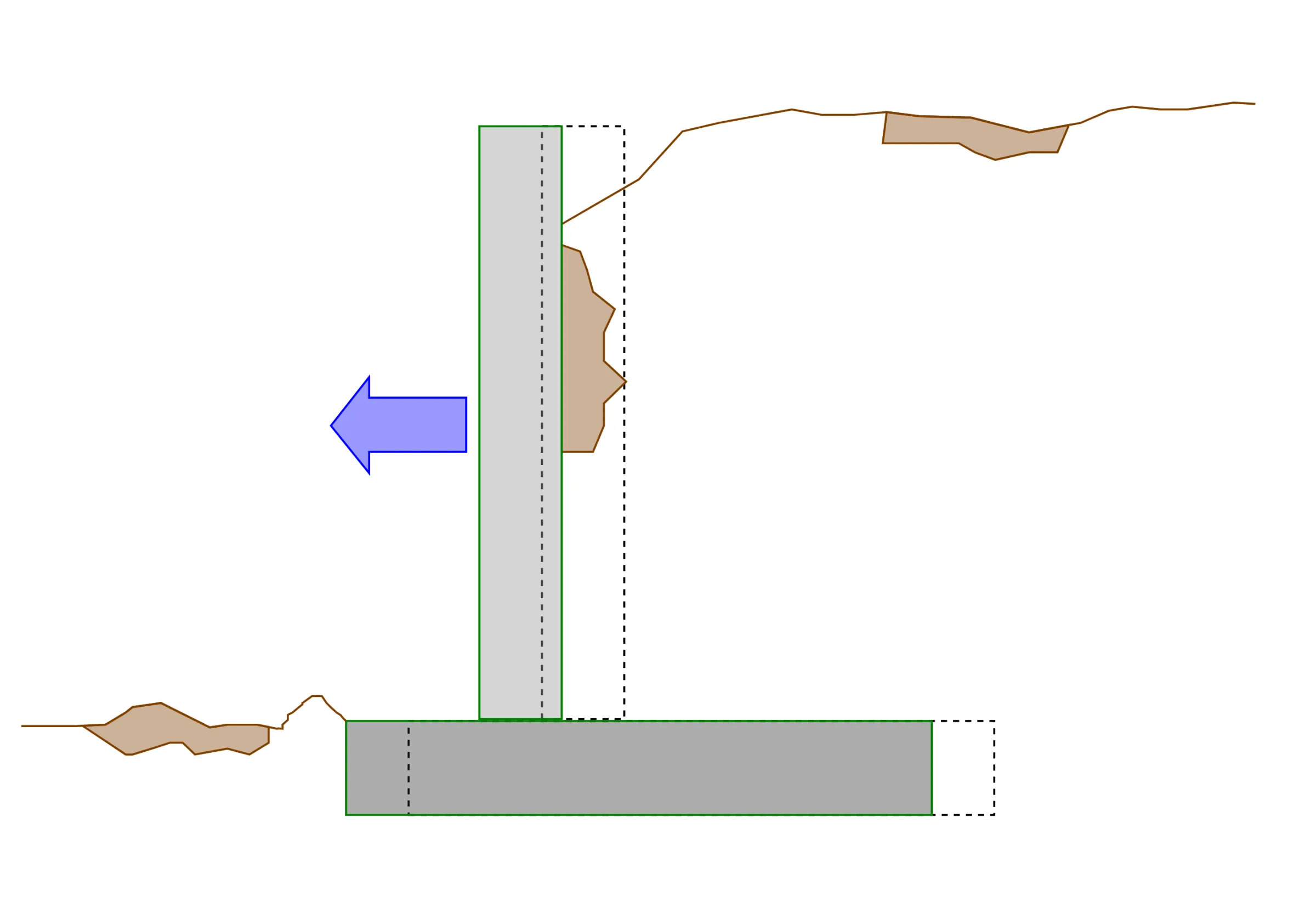
Similarly with rotation failure, we can also now take a look at the forces acting on the wall which are stabilising it and destabilising it for this form of failure…
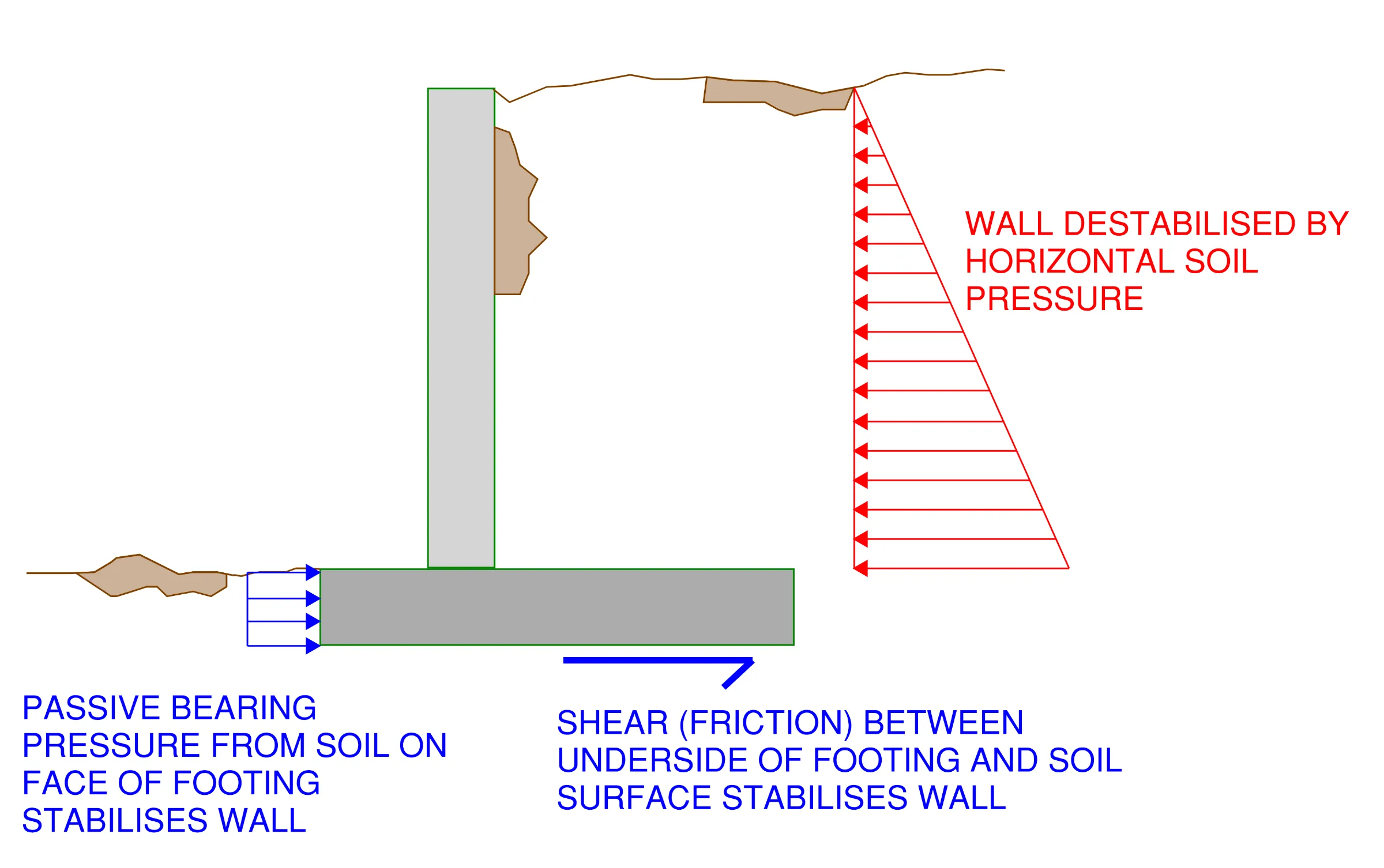
The diagram above simplifies the forces acting on the wall considering sliding failure mechanism. In dot point form we have…
The horizontal component of the soil pressure tends to slide the wall (destabilises the wall)
Friction acting between the bottom face of the footing and the soil surface prevents the wall from sliding (stabilises the wall)
Passive bearing of the soil on the front footing face prevents the retaining wall from sliding (it stabilises the wall).
Again, applying the principles of equilibrium, let's take a look at what can go wrong to cause this type of failure…
Too Much Destabilising Force
The destabilising forces remain the same as they were for the rotation failure. Therefore, the causes for too much destabilising forces are also the same (higher density backfill, insufficient sub-soil drainage or very high surcharge loading)
Insufficient Stabilising Forces
The stabilising forces for sliding failure differ from rotation failure of a retaining wall. Insufficient stabilising forces on the retaining wall which may cause sliding failure may be due to:
Plan area of the footing has been sized too small resulting in low contact area between footing and soil therefore resulting in low friction capacity against failure
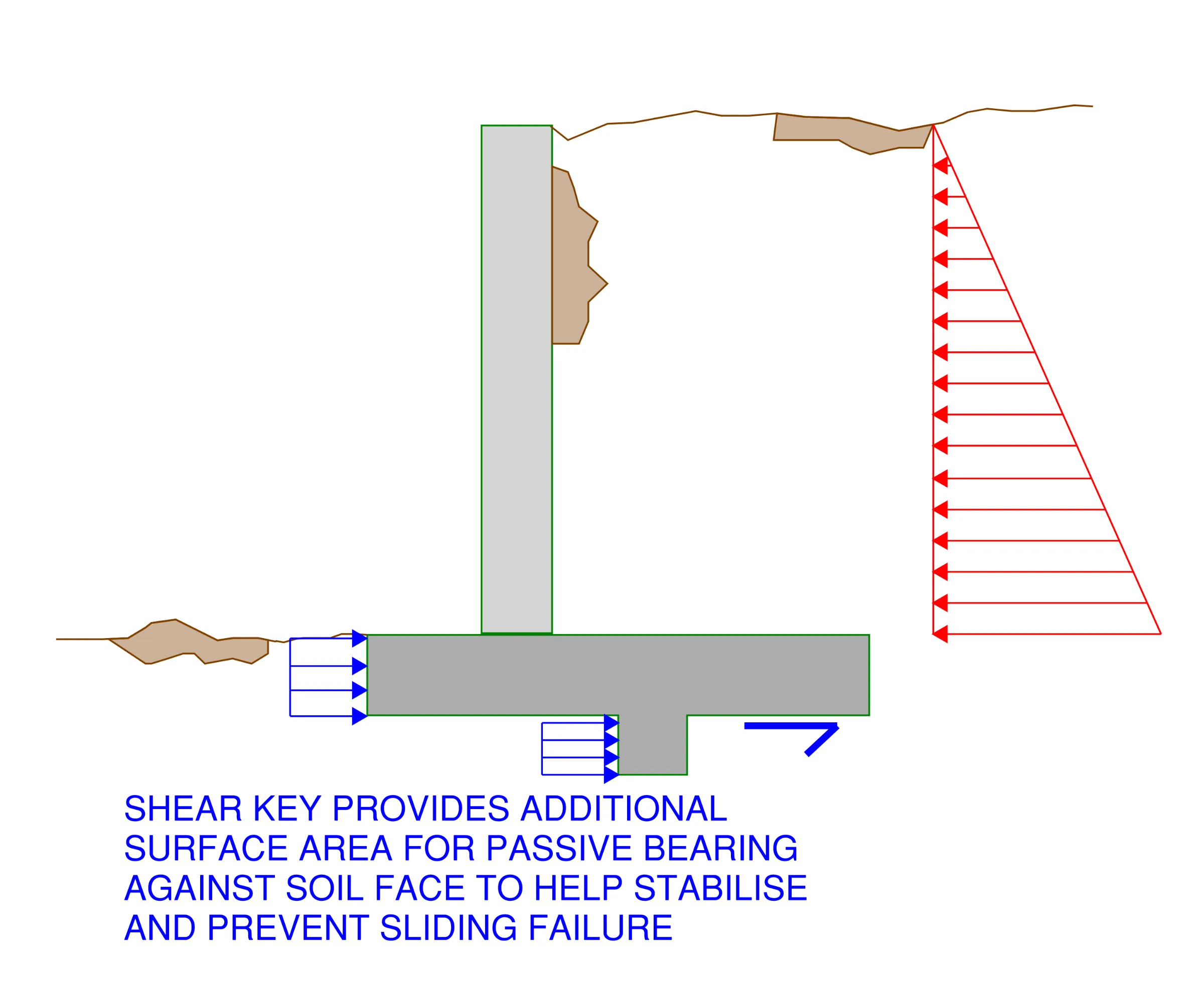
Footing depth is insufficient which results in insufficient surface area for the passive soil bearing to act upon. This can be prevented through the introduction of a shear key. The shear key provides more surface area to bare against to prevent sliding failure from occurring
Global Failure of L-Wall Retaining Walls
Global stability failure can occur in almost all types of retaining walls. It generally occurs for retaining walls which are located on the side of a moderately steep slope.
Rather than failure of the retaining wall itself, it is global stability failure of the soil mass surrounding the retaining wall. The behaviour of this failure is very similar to what you see in land-slides that occur on hillsides.
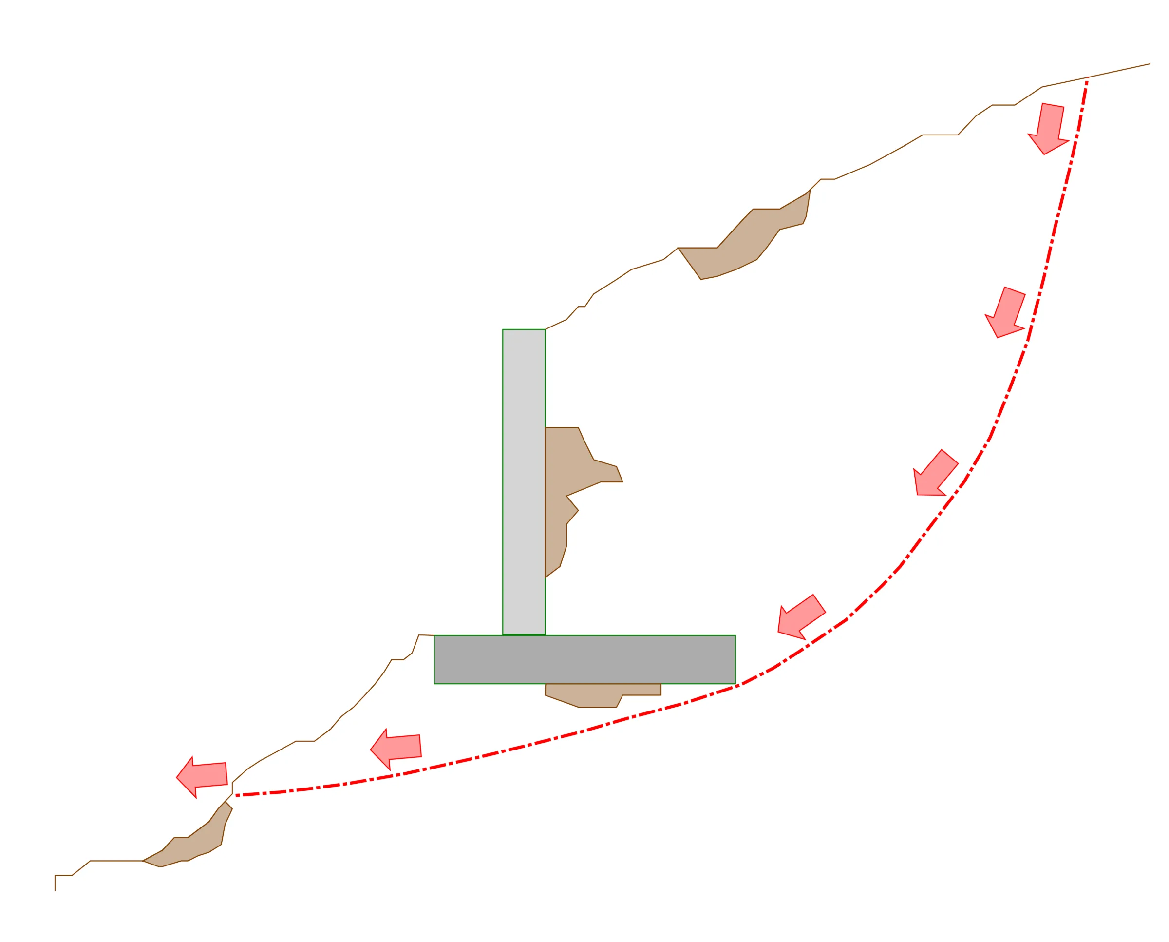
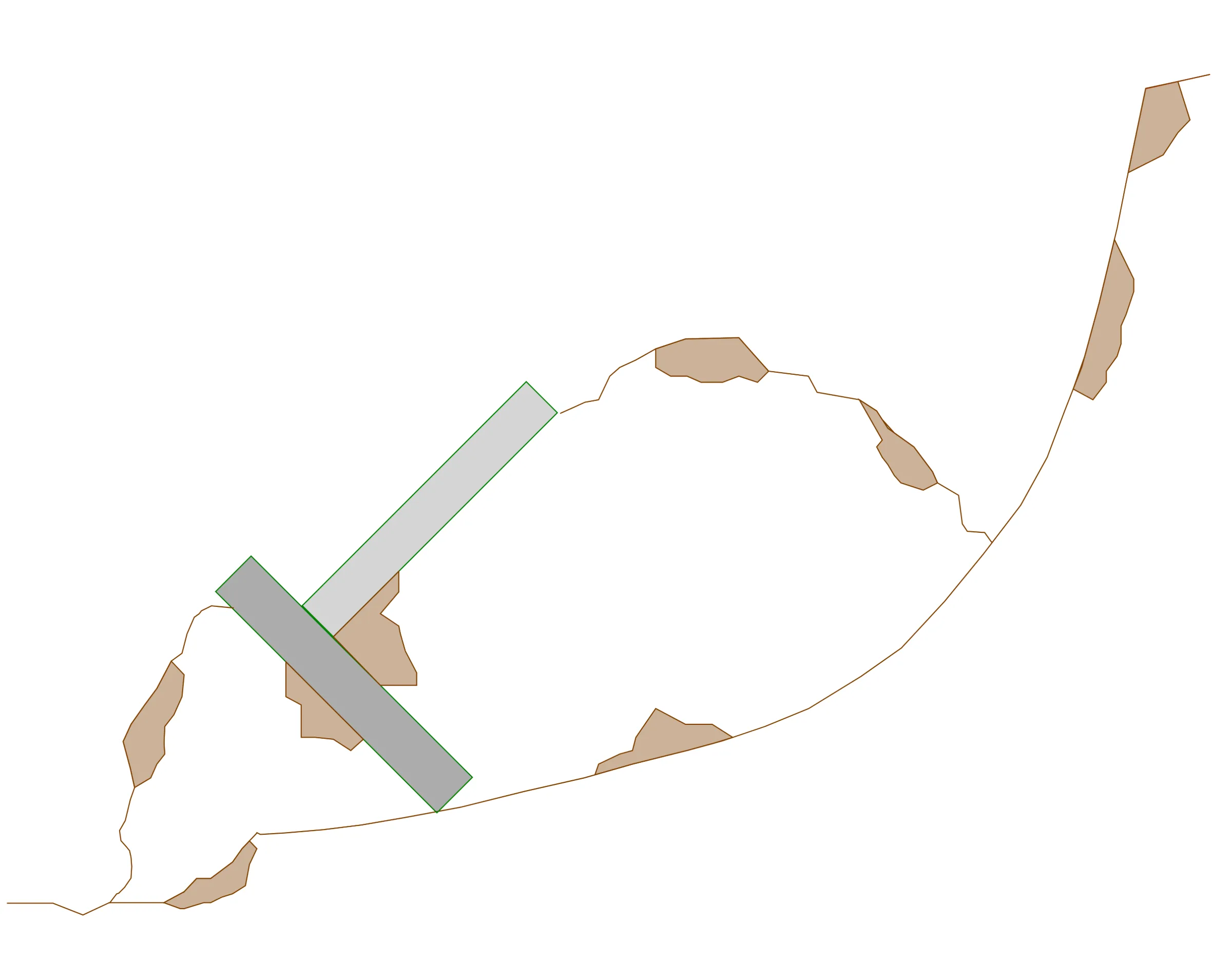
Global stability failure can be caused by the following factors:
Insufficient soil investigation being carried out prior to the design
Earthquake which causes soil movement and shear failure through ground shaking
Excessive moisture build-up in soil structure
Tree removal from slope
Incorrect choice of retaining wall type
Member Failure of L-Wall Retaining Walls
The final possible failure type of fan L-Wall is local member failure. This is failure of either the wall component or the footing component through either fracture of the reinforcing steel or crushing of the concrete.
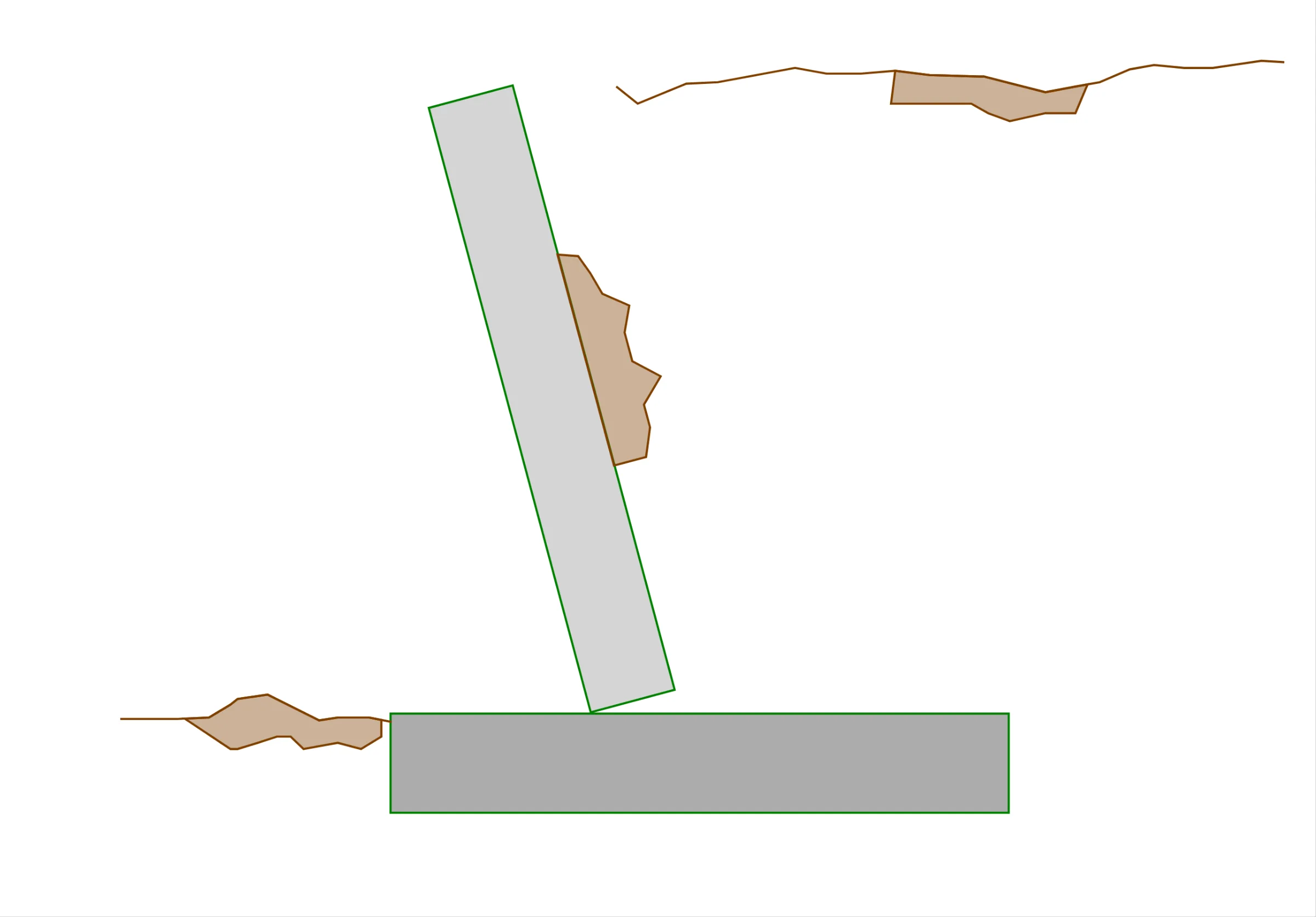
Member failure usually occurs in an L-Wall retaining wall where the wall portion meets the footing. Here there are a number of potential causes for failure:
In moist soil conditions, if the joint is not adequately sealed, the reinforcement can corrode which causes deterioration of the bars and oxide jacking.
Inadequate cover provided between edge of reinforcing bar and dirt face of wall which can also cause corrosion of the reinforcement
Insufficient quantity of reinforcement specified by the Structural Engineer
In-sufficient development of reinforcing bar from the wall to the footing.
The final dot point above, in-sufficient development of reinforcing bar is an issue I’ve seen often overlooked by Structural Engineers. For an in-depth article about pull-out failure and reinforcement development, take a look at THIS article.
Let's take a closer look at the wall-footing joint for this specific application….
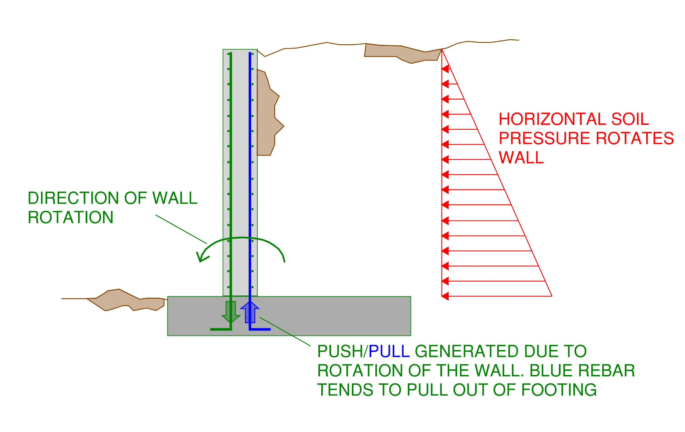
The horizontal soil pressure on the wall generates a push-pull coupling at the base of the wall. The blue reinforcing bar resists the pulling action through tension causing the reinforcing bar to pull out of the footing. If the blue reinforcing bar is not adequately embedded within the footing, the reinforcing bar may experience pull-out or cone failure. To prevent this from occurring, the following measures can be put into place…
Deepen the footing which allows for longer embedment of the reinforcing bar which increases its pull-out capacity
Specifying smaller diameter reinforcing bars but a higher quantity. Smaller diameter rebar requires less development length.
Thickening the wall increases the effective depth of the bending member which results in less tension demand on the blue reinforcing bar highlighted in the previous image. Less tension results in less pull-out force on the bar.
Failure of Soldier Pile Retaining Walls
Another very common type of retaining wall is the Solider Pile Wall. Similarly with the L-Wall retaining wall, the soldier pile wall can come in a couple of different variants…
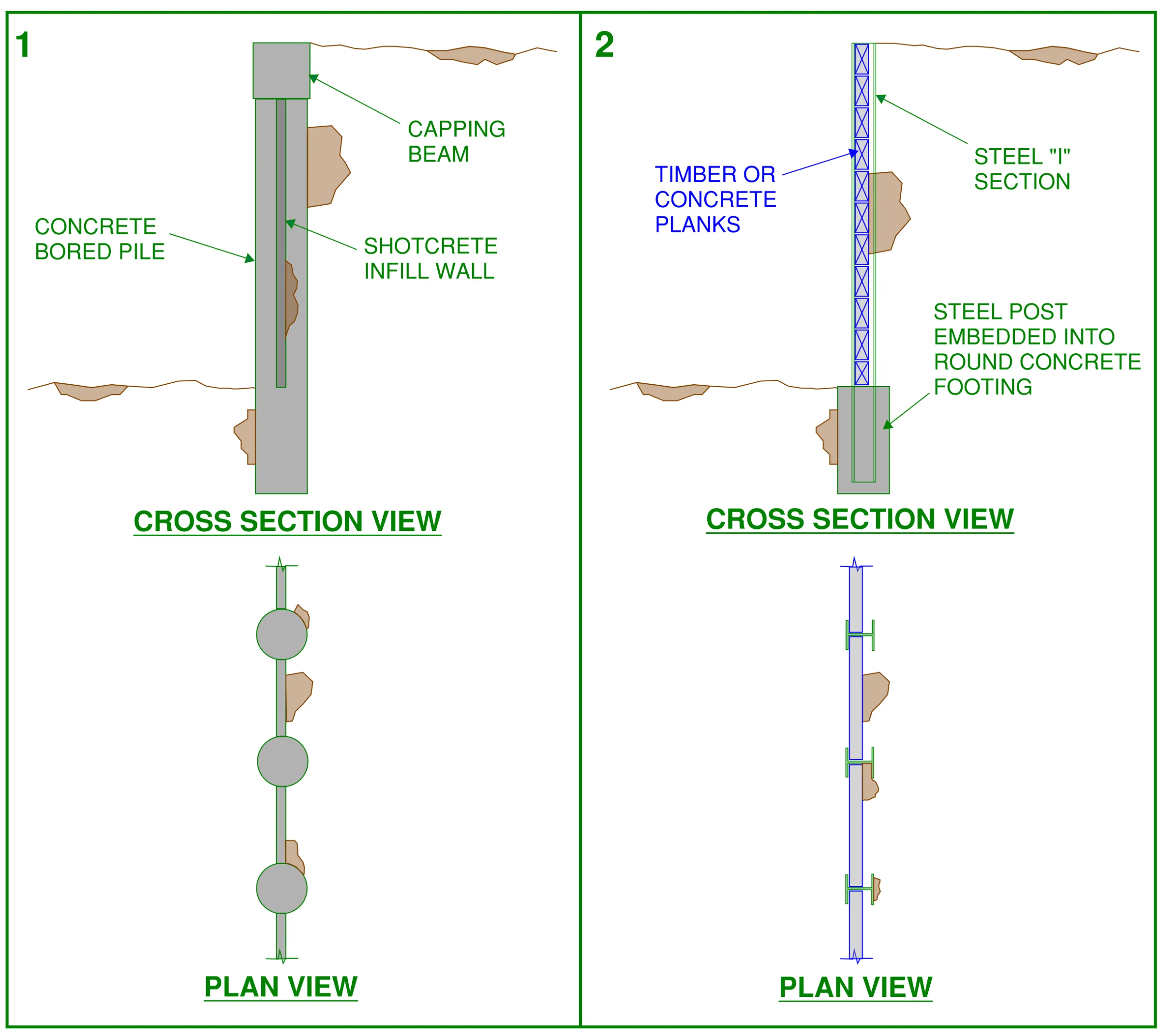
Soldier pile retaining walls are commonly used in basement wall construction. There are further intricacies and variations when discussing soldier pile walls in the context of basements. For a deep dive into these intricacies and variations, take a look at THIS article which covers all you need to know about soldier pile retaining walls.
For our discussion on possible reasons soldier pile retaining walls fail, lets use variant 1 illustrated in the previous image.
Rotation Failure of Soldier Pile Retaining Walls
A common way that soldier pile retaining walls fail is through rotation. Let's see what this looks like specifically for a soldier pile retaining wall…
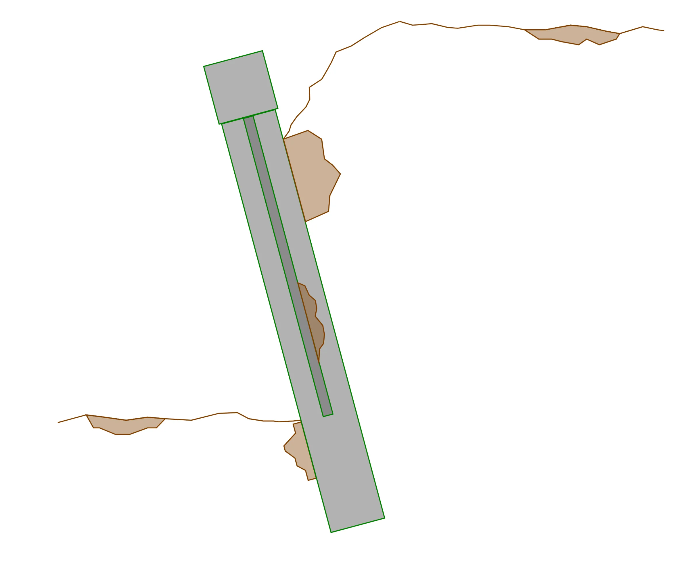
To understand what may cause this rotation failure, let's take a look at the soldier pile wall again pre-failure. Similar with the L-Wall retaining wall, there are forces which tend to stabilise and destabilise the soldier pile wall, let's take a look at a simplified arrangement of this…
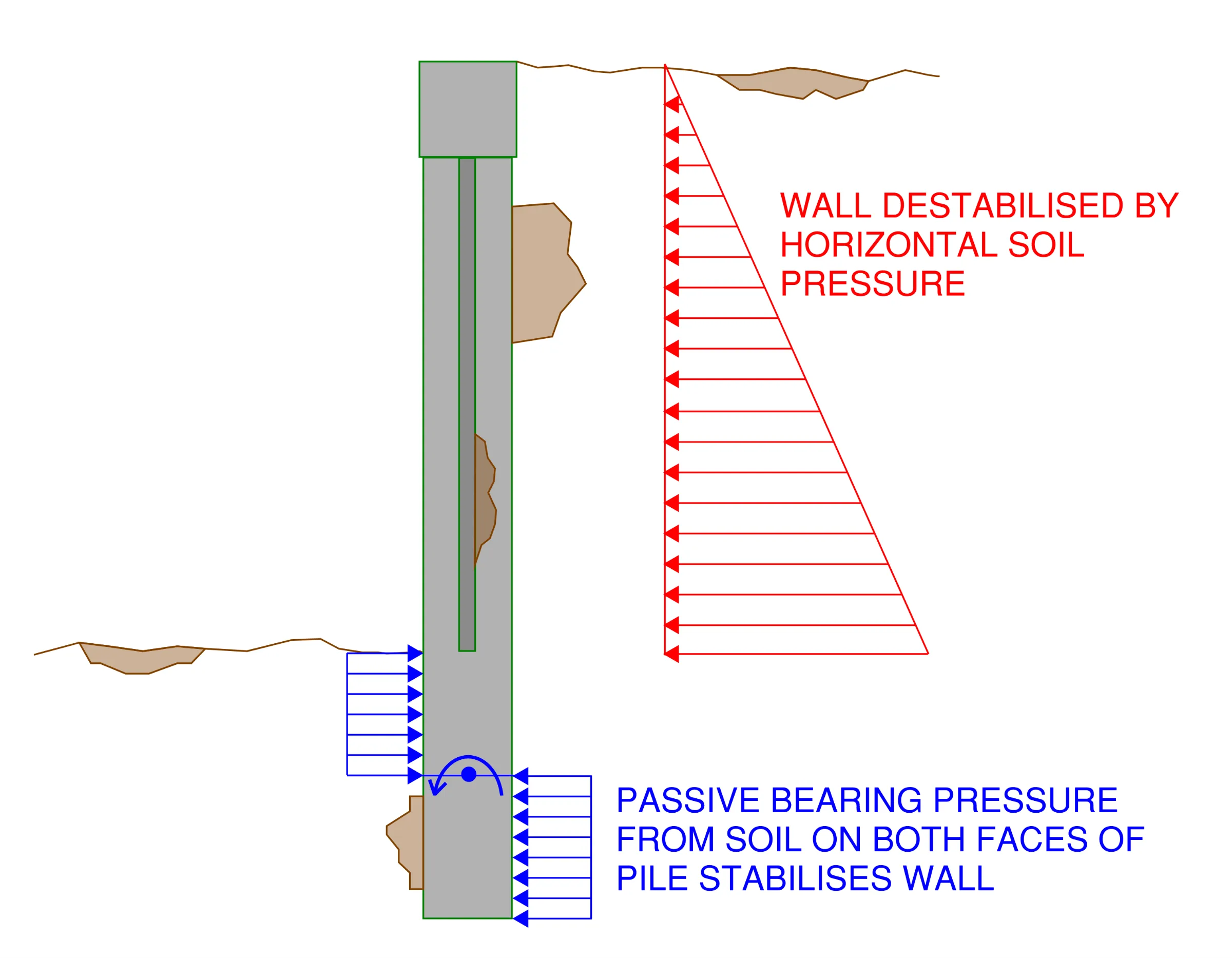
The diagram above simplifies the forces acting on the wall considering rotation failure mechanism. In dot point form we have…
The horizontal component of the soil pressure tends to rotate the wall (destabilises the wall)
Passive bearing pressure against opposing sides of the portion of the pile imbedded in the soil prevents the wall from rotating (stabilises the wall)
Again using the principles of equilibrium, let's take a look at what can go wrong to cause this type of failure for solider pile retaining walls…
Too Much Destabilising Force
The destabilising forces remain the same as they were for the L-Wall retaining wall. Therefore, the causes for too much destabilising forces are also the same (higher density soil than anticipated, insufficient sub-soil drainage or very high surcharge loading). An additional cause unique to a solider pile walls is:
Piles spaced too far apart. Higher pile spacing results in higher soil load being attracted to each individual pile.
Insufficient Stabilising Forces
Insufficient stabilising forces on the solider pile retaining wall which may cause rotation failure may be due to:
Insufficient embedment of the pile toe into the soil. A shorter length results in less surface area for passive soil bearing which results in less capacity.
Pile diameter is too small. Again a smaller diameter results in less surface area for passive soil bearing.
Insufficient soil investigation being performed prior to the design. If the soil bearing capacity is less than anticipated during the design this may result in rotation failure.
Rotation Failure of a Soldier Pile Wall with Ground Anchor.
A soldier pile wall is often coupled with a permanent or temporary ground anchor near the top which assists in stabilising the wall. This alters the support condition to become similar to a propped cantilever rather than a pure cantilever. Let's take a look at the force diagram again with a ground anchor introduced…
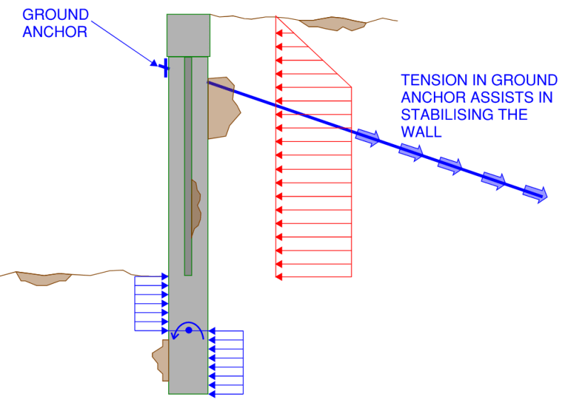
Note that the soil load distribution shape is also changed for this arrangement. Introduction of the ground anchor prevents the tip of the wall to deflect which results in passive soil pressure as opposed to active soil pressure acting on the back of the wall.
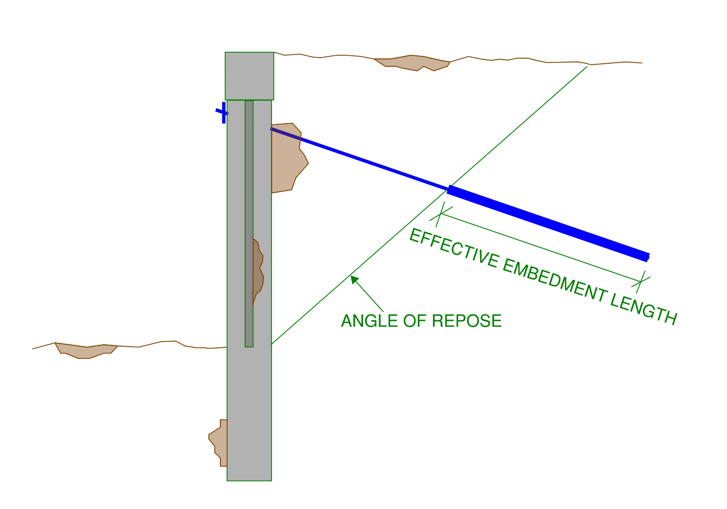
Rotation failure can also occur with this arrangement if the ground anchor is not adequately embedded beyond the angle of repose. The line angle of repose being a line drawn from the base of the wall at an angle equal to the soils internal friction angle (the angle at which the soil remains self-supporting due to internal friction capacity).
Tagged
Never miss a new insight.
Receive email notifications when new articles, project lessons and technical insights are published.
Leave a message.
A thought, a question or a correction on this article — it comes straight to our team. Messages are reviewed by us before they appear beneath the article.
Tell us about your building.
Can’t find the answer you’re looking for? Tell us about your building, project or challenge and we’ll help point you in the right direction.
About The Author

Quentin Suckling
Director - Structural Engineering
Quentin Suckling is the Director and Principal Structural Engineer at Sheer Force Engineering. Passionate about heritage preservation and adaptive reuse, he enjoys understanding how buildings behave and helping clients unlock the potential within existing structures. Through these articles he shares practical lessons from projects, investigations and engineering practice.